
RX 7 Help
RX 7 Overview
iZotope’s award-winning RX Audio Editor is the industry standard for audio repair, restoration, and enhancement. It offers a comprehensive suite of tools focused on alleviating common to complex audio issues. Post production professionals, audio engineers, and video editors alike use RX to transform problematic recordings into production-ready audio.
This help guide is shared by RX 7 Elements, RX 7 Standard and RX 7 Advanced. The following tags are used throughout the manual to differentiate the feature sets:
- [STD & ADV] Indicates that a feature is included in RX 7 Standard and RX 7 Advanced.
- [ADV] Indicates that a feature is exclusive to RX 7 Advanced.
The following tables outline the differences between Elements, Standard, and Advanced. The rightmost column in each of the tables indicates features that are new or improved in RX 7.
RX 7 Audio Editor Feature Comparison
| Features | Elements | Standard | Advanced | |
|---|---|---|---|---|
| Batch Processor | X | X | X | |
| Clip Gain | X | X | X | |
| Composite View | X | X | ||
| Find Similar | X | X | ||
| Instant Process | X | X | ||
| Markers & Regions | X | X | X | |
| Module Chain | X | X | X | Improved |
| Module List View Filters | X | X | X | |
| MP3 Export | X | X | ||
| Multichannel Processing | X | New! | ||
| Plug-in Hosting | X | X | X | |
| Recording & Monitoring | X | X | X | |
| Repair Assistant | X | X | X | New! |
| Spectrum Analyzer | X | X | X | |
| Spectral Editing Tools | X | X | X | |
| Waveform Statistics | X | X | X |
RX 7 Module Comparison
| Module Name | Elements | Standard | Advanced | New/Improved |
|---|---|---|---|---|
| Ambience Match | X | |||
| Azimuth | X | |||
| Breath Control | X | X | ||
| Center Extract | X | |||
| De-bleed | X | X | ||
| De-click | X | X | X | |
| De-clip | X | X | X | |
| De-crackle | X | X | ||
| De-ess | X | X | ||
| De-hum | X | X | X | |
| De-plosive | X | X | ||
| De-reverb | X | X | ||
| De-rustle | X | |||
| De-wind | X | |||
| Deconstruct | X | |||
| Dialogue De-reverb | X | New! | ||
| Dialogue Isolate | X | Improved | ||
| Dialogue Contour | X | New! | ||
| Dither | X | X | ||
| EQ | X | X | ||
| EQ Match | X | |||
| Fade | X | X | X | |
| Gain | X | X | X | |
| Interpolate | X | X | ||
| Leveler | X | |||
| Loudness | X | |||
| Mixing | X | X | X | |
| Mouth De-click | X | X | ||
| Music Rebalance | X | X | New! | |
| Normalize | X | X | X | |
| Phase | X | X | X | |
| Resample | X | X | ||
| Signal Generator | X | X | X | |
| Spectral De-noise | X | X | ||
| Spectral Repair | X | X | ||
| Time & Pitch | X | X | ||
| Variable Pitch | X | X | Improved | |
| Variable Time | X | X | New! | |
| Voice De-noise | X | X | X |
RX 7 Plug-in Comparison
| RX Plug-ins | Elements | Standard | Advanced | |
|---|---|---|---|---|
| Ambience Match | X | |||
| Breath Control | X | X | New! | |
| Connect | X | X | ||
| De-click | X | X | X | |
| De-clip | X | X | X | |
| De-crackle | X | X | ||
| De-ess | X | X | ||
| De-hum | X | X | X | |
| De-plosive | X | X | ||
| De-reverb | X | X | ||
| De-rustle | X | NEW! | ||
| Dialogue Isolate | X | NEW! | ||
| Monitor | X | X | ||
| Mouth De-click | X | X | ||
| Music Rebalance | X | X | NEW! | |
| Spectral De-noise | X | X | ||
| Voice De-noise | X | X | X |
Working with Files
Opening Files
RX supports opening up to 16 audio files at a time. Files can be opened in the RX Audio Editor using the following methods:
- Navigate to the File menu, select “Open…” and choose the files from the system dialog that appears. Alternatively, the following keyboard shortcuts can be used to launch the “Open…” system dialog: Command+O (Mac) or Ctrl+O (Windows).
- Drag and drop files into the main editor window to open them in a new file tab.
- Drag a file from Finder/Windows Explorer onto the RX Audio Editor icon in the Dock/Desktop.
- Click on the “Open file” button that appears in the RX Audio Editor window when no files are loaded.
- Double-click on the RX logo in the middle of the RX Audio Editor interface when no files are loaded.
Supported File Formats
A number of different file formats can be opened and edited in the RX Audio Editor. The next three sections outline the supported file formats and channel count configurations that can be opened in the RX Audio Editor. For information about file formats when saving or exporting files in RX, see the Saving Files and Exporting Files sections below.
Supported Audio File Formats
The following audio file formats can be opened in the RX Audio Editor: AAC, AAX (Audible Audiobook Format), AIFF/AIF, BWF, CAF, FLAC, M4A, MP3, OGG, SD2, WAV, WMA
Supported Video File Formats
The RX Audio Editor supports loading video file formats, but does not support video playback. When a video file is opened in RX, only the audio data from that file will be imported.
The following video file formats can be opened in the RX Audio Editor: AVI, M4V, MOV (RX requires that Quicktime is installed in order to open Quicktime file formats, e.g. .mov files.), MPEG, MPV, WMV
File Format Dependencies
Some file formats may have dependencies based on your operating system that may prevent you from importing them into the RX Audio Editor. For example, Windows native formats (like WMA and WMV) may not open on Mac and QuickTime formats (like AAC, MOV, and M4V) may require installing QuickTime on Windows and running the RX Audio Editor in 32-bit mode.
Supported Channel Configurations
The RX 7 Elements Audio Editor and RX 7 Standard Audio Editor support opening mono and stereo audio files.
Tip: Option for opening Split Stereo files in one tab
Mono audio files with (.L and .R) or (.1 and .2) extensions can be opened as either mono files (2 mono tabs) or split stereo (1 stereo file tab). See Preferences > Misc for more information. Note that this option is only applicable to split stereo files and does not apply to split surround files.
Multichannel File Support
The RX 7 Advanced Audio Editor supports opening audio files with up 10 channels per file tab. Multichannel audio device settings can be configured in the “Audio” tab of the Preferences menu.
The channel selector labels can be configured by selecting an option in the Channel Order menu. To access the Channel Order menu, right-click on the Time ruler and navigate to the “Channel Order” sub-menu. The options available in the Channel Order menu depend on the number of channels in the active file tab.
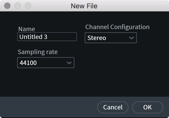
Creating New Files
To create a new file in RX:
- Open the File menu
- Select “New…”
- You will be prompted for the name, sample rate and channel count of the new file you are creating.
Tip: Create a new file from the contents of the clipboard
If you have existing audio data in your clipboard (for example, if you have copied a selection from an existing file in RX), you can create a new file based on that audio data.
- Open the “File” menu, choose “New from Clipboard” or use the keyboard shortcut: Command+Shift+N (Mac) or Ctrl+Shift+N (Windows)
The new file will match the sample rate and channel count of the audio data present on your clipboard.
Managing File Tabs
RX supports having up to 16 files open at once. You can navigate between tabs by clicking on a tab or using the following keyboard shortcuts:
- Select tab to the right of current tab: Control+Tab (Mac) or Alt+Tab (Windows)
Select tab to the left of current tab: Control+Shift+Tab (Mac) or Alt+Shift+Tab (Windows)
If you have multiple files open, an arrow button will appear to the right of the last visible tab. You can access file tabs that are not currently visible by clicking on the arrow button and selecting a tab from the menu.
Saving Files
There are a number of ways to save a file in the RX Audio Editor. The Save Operations include:
| Name | Description | Default Mac Shortcut | Default Windows Shortcut |
|---|---|---|---|
| Save | For uncompressed file formats (.wav or .aiff): Overwrites the original file on disk | Command+S | Ctrl+S |
| For compressed file formats: Opens the Export File dialog | Command+S | Ctrl+S | |
| Save As… | For uncompressed file formats (.wav or .aiff): Save a copy of your file using the same file format | Command+Shift+S | Ctrl+Shift+S |
| For compressed file formats: Opens the Export File dialog | Command+Shift+S | Ctrl+Shift+S | |
| Save RX Document | Saves file as .rxdoc file extension (more information below) | ||
| Save RX Document As… | Saves copy of your .rxdoc file |
Autosave
The RX Audio Editor will automatically save backups of your editing session by default. When the RX application is launched, it will open your most recent editing session. The option to turn it off is located under the Preferences > Misc tab as “Resume last editing session when app starts.”
Saving RX Documents
You can save a file using the RX Document file format (.rxdoc) to archive your edits. An RX Document includes your original file, all the edits you’ve made to it, and your most recent selection and view state. RX Documents can only be opened in the RX Audio Editor. If you need to save your file so it can be opened somewhere else (like a DAW or media player), you need to export it in another format (like WAV or AIFF).
To save an RX Document, select File > Save RX Document… and select where you would like to store the file.
Keep in mind that the size of the RX Document file can be very large, especially if your list of edits include multiple processes on the whole file.
Export Options
There are a number of different export options in the RX Audio Editor:
Export File

- Select File… > Export
- Select the file format you want to Export to and adjust the associated settings as desired (available settings explained in the table below)
- Click “OK”
- In the system window, name your file and choose where you would like to save it to
- Click “Save” to export your file
Tip
- Checking the Reopen file in RX checkbox will open your exported file in the RX 7 Audio Editor after the export completes successfully
Export Format Options
The following file formats are available when exporting files from the RX 7 Audio Editor:
- WAV - Uncompressed
- AIFF - Uncompressed
- FLAC - Compressed: Lossless Compression
- OGG - Compressed: Lossy Compression
- MP3 [STD & ADV] - Compressed: Lossy Compression
Uncompressed File Formats
The RX 7 Audio Editor allows you to export files to the following uncompressed file formats: WAV and AIFF.
WAV
The following options are available when exporting files to this file format:
- Bit Depth: Determines the bit depth of the exported file.
- Choices include: 16 bit, 24 bit, 32 bit (float), 32 bit (int).
- Choices include: 16 bit, 24 bit, 32 bit (float), 32 bit (int).
- Dither: Determines the Dither Type to be applied to the exported file.
- Choices include: None, White Noise (TPDF), Noise shaping (MBIT+)
- Choices include: None, White Noise (TPDF), Noise shaping (MBIT+)
- BWF: When selected, the file will be exported with extended information that is included in the file header of a Broadcast Wave File.
- Preserve Non-Audio Data: When selected, the exported file will retain the metadata of the original file.
AIFF
The following options are available when exporting files to this file format:
- Bit Depth: Determines the bit depth of the exported file.
- Choices include: 16 bit, 24 bit, 32 bit (float), and 32 bit (int).
- Choices include: 16 bit, 24 bit, 32 bit (float), and 32 bit (int).
- Dither: Determines the Dither Type to be applied to the exported file.
- Choices include:** None, White Noise (TPDF),** and Noise shaping (MBIT+).
- Choices include:** None, White Noise (TPDF),** and Noise shaping (MBIT+).
- Preserve Non-Audio Data: When selected, the exported file will retain the metadata of the original file.
Compressed File Formats
The RX 7 Audio Editor allows you to export files to the following compressed file formats: FLAC (Lossless Compression), OGG Vorbis (Lossy Compression) and MP3 (Lossy Compression).
FLAC (Lossless)
The FLAC file format offers lossless compression. The following options are available when exporting files to this file format:
- Bit Depth: Determines the bit depth of the exported file.
- Choices include: 8 bit, 16 bit, and 24 bit
- Choices include: 8 bit, 16 bit, and 24 bit
- Dither: Determines the Dither Type that will be applied to the exported file.
- Choices include: None, White Noise (TPDF), and Noise shaping (MBIT+)
- Choices include: None, White Noise (TPDF), and Noise shaping (MBIT+)
- Compression Level: Adjusts the compression strength of the FLAC encoder. Stronger compression requires more CPU time during file encoding but results in a slightly smaller file. FLAC compression setting does not result in any quality change to the signal since FLAC is a lossless format.
OGG (Lossy)
The Ogg Vorbis file format offers lossy compression. The following options are available when exporting files to this file format:
- Quality: AAdjusts the bitrate of the Ogg Vorbis compression algorithm. Higher bitrate values result in higher audio quality, but also increase the file size
- Prevent Clipping: See the Prevent Clipping section below for more information.
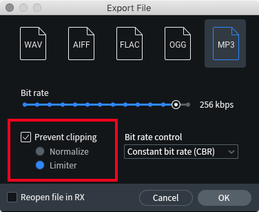
MP3 (Lossy)
The mp3 file format offers lossy compression. The following options are available when exporting files to this file format:
- Bit rate: Adjusts the bit rate of the MP3 compression algorithm. Higher bit rates result in higher quality audio but will increase the file size.
- Bit rate control: Determines how (or if) bit rate varies over time.
- Choices include: Constant bit rate (CBR), Average bit rate (ABR), and Variable bit rate (VBR).
- Choices include: Constant bit rate (CBR), Average bit rate (ABR), and Variable bit rate (VBR).
- Prevent Clipping: See the Prevent Clipping section below for more information.
Prevent Clipping
Predicts and prevents codec clipping when exporting audio in lossy formats (MP3 and OGG) by checking for decoded levels and adjusting levels of the original signal.
Prevent Clipping Processing Time
- Prevent Clipping may run significantly slower than regular encoding, since it computes the correct level adjustment depending on the amount of clipping occurring in the file.
- Files with little to no codec clipping usually will encode quickly, whereas heavily clipping files may take longer.
There are two types of file level adjustments that can be applied:
- Normalize: attenuates overall level of the file to ensure that the encoded/decoded file does not exceed 0 dBTP.
- Limiter: attenuates parts of the file that could become clipped to retain the level of non-clipping sections, while overall true peak levels are limited to 0 dBTP.
Choosing Normalize or Limiter
- The Limiter will leave larger sections of the file unchanged in level and will only attenuate sections that would experience clipping. However, like any dynamic processing, this may create pumping.
- The Normalize mode can completely avoid pumping at the expense of slightly reducing the overall level of the file.
Export Selection
This option will allow you to export only the audio that is contained within your current selection, as opposed to the entire audio file.
- Select File > Export Selection, and the Export File dialogue box appears.
- Follow the additional aforementioned steps.
Export Regions to Files
This option allows you to export multiple regions of any audio file that has regions as discrete audio files. To export regions:
- Select File > Export Regions to Files.
- Choose the exported file format in the Export window
- In the File Save dialogue box, navigate to where you want to save the files.
- If you want, enter a prefix for your series of files in the Optional prefix field.
Note
- If you choose not to add a prefix, the names of the files will be the names of the regions. If any regions have the same name, numbers will be appended sequentially.
- If you choose not to add a prefix, the names of the files will be the names of the regions. If any regions have the same name, numbers will be appended sequentially.
- Click Save.
Export Screenshot
This option allows you to export your current Spectrogram/Waveform display as a PNG image file. This can be very helpful for archiving any restoration process or for forensic documentation.
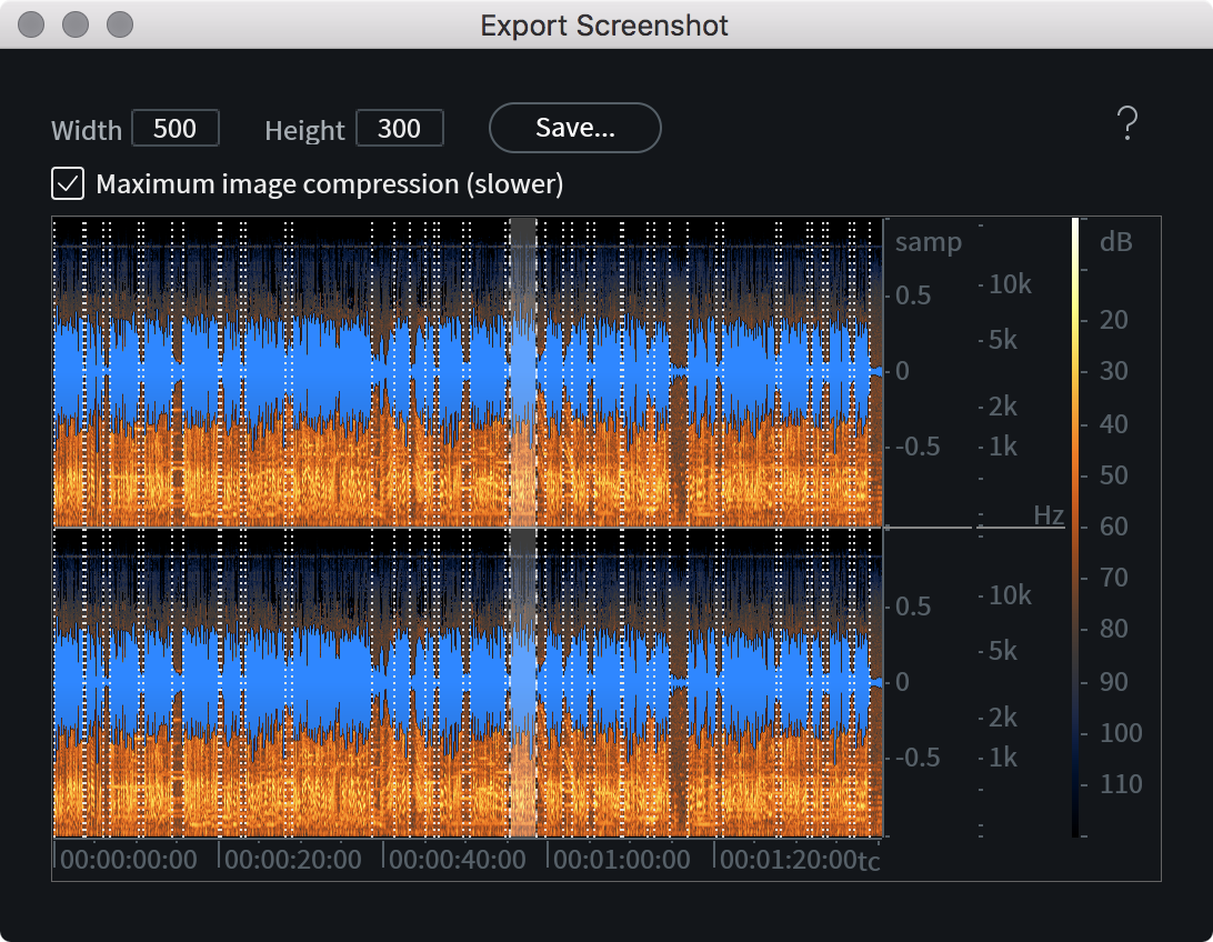
When clicking on Export Screenshot from the File menu, your current Spectrogram/Waveform view will be used for adjusting your screenshot size and position.
Note
The Spectrogram/Waveform transparency balance must be set before selecting File > Export Screenshot as this cannot be changed in this window.
To define the size of your screenshot, simply click and drag in order to enlarge or shrink the screenshot window. The dimensions of your resulting screenshot will update automatically, however these can also be entered manually by clicking once in either Width or Height.
Note
The max resolution attainable for your screenshot will be limited by the individual computer’s screen resolution.
When you are finished changing the dimensions of your screenshot, click on the Save button to name and save your .PNG screenshot to your chosen directory.
Tip
To save screenshots faster (at the expense of having a larger file on disk), disable Maximum image compression.
Export History as XML
Export the Undo history list of your current file tab to an .xml document.
File Info
The File Info window can be opened by navigating to Window menu > File Info. There are two sections in the File Info window: General Info and More Info. The More Info section lists information dependent on the file type. The following information is available in the General Info and More Info sections of the File Info window:
- General Info
- Name: The current filename
- Duration: Length of the file
- Sampling rate: The original sampling rate of the file
- Bit depth: The original bit depth of the file
- Channels: Mono or stereo
- Size on disk: Size of the file in bytes
- Name: The current filename
- More Info
- Timecode
- Created by
- Originator reference
- Date created
- Time created
- BWF version
- Coding history
- Track Title
- Artist
- Album
- Date
- Track Number
- Comment
- Genre
- Timecode
Closing Files
The following sections describe different methods availble for closing file tabs in the RX Audio Editor.
Close One File Tab
Single file tabs can be closed using the following methods:
- Single-click on the ‘x’ button in the file tab display
- Select the “Close file” option in the File menu
- Right-click on any file tab and select “Close” from the context menu
- Keyboard shortcuts: Command+W (Mac) or ctrl+W (Windows)
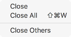
Close Other File Tabs
To keep one file tab open and close all other file tabs:
- Right-click on the file tab that should remain open and select “Close others” from the context menu
Close All File Tabs
All file tabs can be closed using the following methods:
- Select the “Close all files” option in the File menu
- Right-click on any file tab and select “Close all” from the context menu
- Keyboard shortcuts: Command+Shift+W (Mac) or ctrl+Shift+W (Windows)
Closing File Tabs With Unsaved Changes
If a file has been edited or processed in the RX Audio Editor and the changes have not been saved, a small dot will appear in the corner of the file tab to indicate that there are unsaved changes.
When closing file tabs that have unsaved changes, a prompt will be displayed before the file is closed. The prompt will include options to save, revert changes or cancel before closing the modified file.

The following options are available in the prompt:
- Yes: The modified file will be saved as an RX Document file (.rxdoc), a system window will appear to select the save location for the file before closing the tab.
- No: Unsaved changes will be discarded and the file tab will be closed.
- Cancel: The prompt will be dismissed and the file tab will remain open.
Closing The Application With File Tabs Open
The RX Audio Editor application will open all file tabs present when it was last closed if the “Reopen previous audio files when app starts” option in the Preferences > Misc tab is enabled.
If this option is enabled and the application is closed when files with unsaved changes are present, a prompt will not be displayed. Any unsaved changes will be stored in the RX session data folder and will load the next time the application is opened.
If this option is disabled, a prompt will appear to save or discard changes when closing the application if any file tab has unsaved changes. A separate prompt will appear for each file tab with unsaved changes. If any of the prompt dialogs are canceled, the application will remain open.
Recording in the RX 7 Audio Editor
Recording
RX supports recording up to two channels at a time.
To record in the RX 7 Audio Editor:
- Create a new file.
- Press the Record button once to arm recording. The Record button will flash red when RX is armed to record. The meters to the right of the transport controls will update based on your input signal when recording is armed.
- Before recording, you should ensure that your input levels are not clipping and allow for adequate headroom.
- Alternatively, you can enable input monitoring to set input levels without engaging record arm.
- Alternatively, you can enable input monitoring to set input levels without engaging record arm.
- After adjusting your input levels, you can start recording by clicking the Record button again. When RX is recording, the Record button will display as solid red.
- You can stop recording by clicking the Record button again.
- After you have stopped recording you can edit and apply processing to the file.
RX 7 Session Data Folder
After recording, your recorded audio data is stored in the RX 7 Session Data folder. You can set the location of the RX Session Data folder in Preferences > Misc tab. If you use the recording functionality in the RX Audio Editor often, it is recommended that the RX Session Data folder be located on a drive with a sufficient amount of free space.
Troubleshooting
If you are having trouble recording in RX, try the following steps:
- Enable Input Monitoring and look for activity on RX’s level meters.
- Close other audio applications, DAWs and NLEs open on your computer to make sure no other program is usurping the sound card.
- Open Preferences > Audio and make sure the correct device is listed in Input Device. Also check in the Channel Routing dialogue to make sure the correct inputs are selected.
- Check your input source. Make sure the hardware connections between whatever you’re recording from and the inputs on your audio interface are correct.
Transport Functions & Displays
Transport

| Name | Description | |
|---|---|---|

|
INPUT MONITOR | When enabled, allows you to monitor input signal to set levels prior to recording. Input source is configured in the RX Audio Editor Preferences |

|
RECORD | Begins recording into a new file. One click puts recording into an armed state for safely setting input levels. The next click begins recording. A third click stops recording. If you already have a file open, hitting Record will prompt you to create a new file for recording. |

|
REWIND [Enter/Return] | Brings you back to the start of the file. |

|
PLAY [Spacebar] | Starts and stops playback. Starts or stops recording if Record is armed. |

|
PLAY SELECTION ONLY | When you’ve made a selection of a time range, frequency range, or both, this button auditions just the selection (useful for isolating intermittent noises, etc.) |

|
LOOP Ctrl+L (Windows) Cmd+L (Mac) | Enable this switch to loop the selected audio. |

|
PLAYHEAD FOLLOWS PLAYBACK Ctrl+R (Windows) Cmd+R (Mac) | Toggles the behavior of the playhead on stop. If this is enabled, the playhead will return to the anchor sample (the position before playback began). |
|
|
PLAYHEAD | To place the playhead, single click anywhere in the Spectrogram/Waveform display. To playback audio while positioning the playhead, click and drag the playhead icon or hold Ctrl (Windows) or Command (Mac) while clicking and dragging in the Spectrogram/Waveform display. |
Time/Frequency Readouts
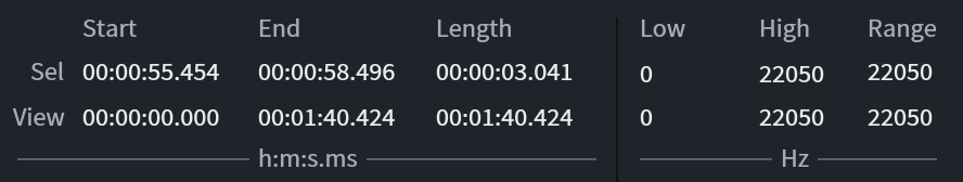
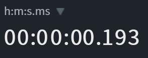
- The time display (on the left in the image above) shows the start, end and length time values of the current selection and the current view. The time format used in this display is selected in the time format menu, explained in the section below.
- The frequency display (on the right in the image above) shows the low frequency boundary, high frequency boundary and frequency range values for the current selection and the current view range.
- Clicking on any of these fields allows you to manually enter values.
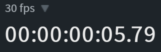
Transport Clock
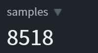
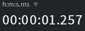
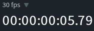
Indicates the current position of the playhead. Depending on time format display setting, this value is shown in hours/minutes/seconds, time code, or samples.
Time Format Display
You can change the time format display used in the time ruler and time readouts. It can be accessed by right-clicking the time ruler or by clicking the arrow button to the left of the currently selected time format label.
| Display | Name & Description |
|---|---|
|
Samples: The sample counter, starting from 0 |
|
Time (h:m:s): Time in hours, minutes, seconds, and milliseconds, starting from 0 |
|
Timecode (n fps): The time code in hours, minutes, seconds, and frames, starting from 0 |
|
Source Time (h:m:s): Time in hours, minutes, seconds, and milliseconds, starting from the clip’s timecode origin |
|
Source Timecode (n fps): The time code in hours, minutes, seconds, and frames, starting from the clip’s timecode origin. The value of n (the frame rate of the time code) is determined by the Time Scale Frame Rate setting in the Misc tab of the Preferences window |
Spectrogram/Waveform Display
Overview
The RX Audio Editor features a rich visual environment for editing and repairing audio. The central focus of the interface is the Spectrogram/Waveform display. It combines an advanced Spectrogram with a waveform transparency overlay to provide frequency and amplitude information in one highly configurable window.
Using the spectrogram to identify audio problems
- See the Identifying Audio Problems chapter for tips on using the spectrogram to spot common audio issues.
Anatomy of the Spectrogram Display
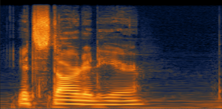
The spectrogram allows you to visualize both frequency and amplitude information of an audio recording in one display.
Frequency
The Spectrogram shows frequency information across the vertical axis. Lowest frequency content is displayed at the bottom, highest frequency content is displayed at the top.
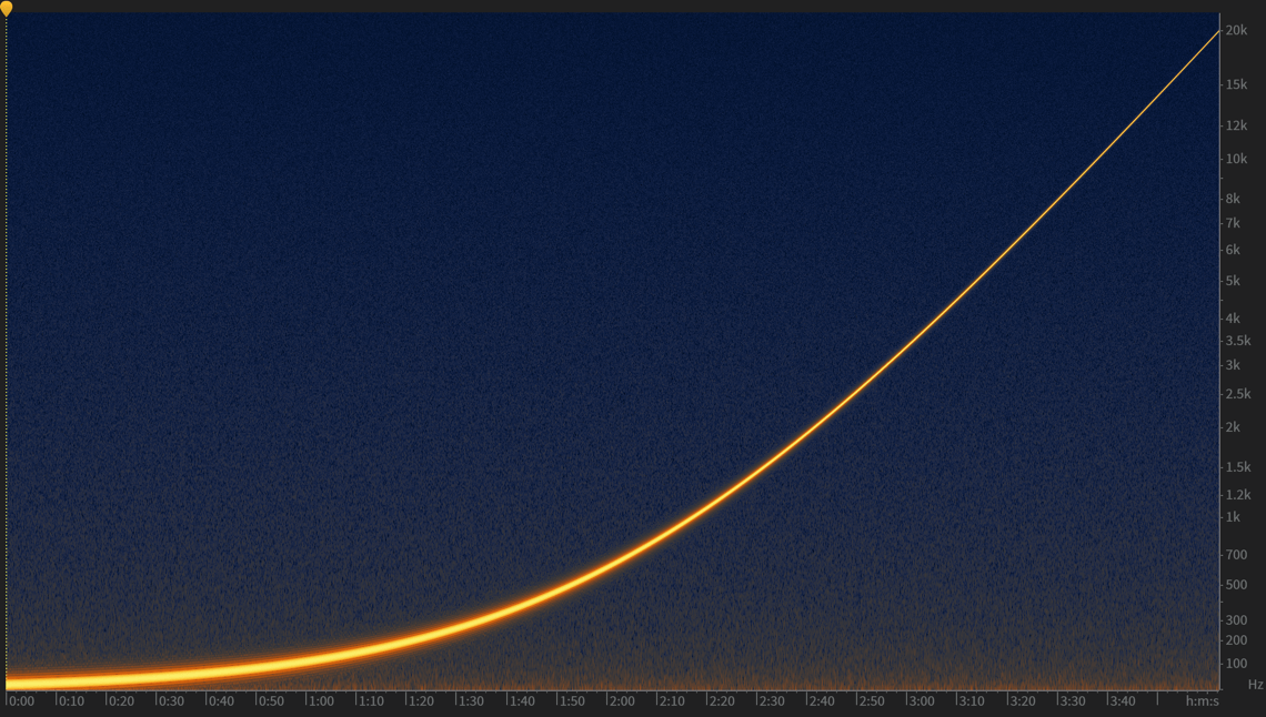
This image shows the spectrogram of a sine sweep over pink noise. The sine sweep starts at 20 Hz (bottom of the display) and sweeps to 20 kHz (top of the display) over 4 minutes.
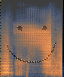
Amplitude and Color
The amplitude of frequency content is indicated by variations in color in the Spectrogram. The color map ruler (to the right of the frequency ruler) shows the color being used to represent a given amplitude value.
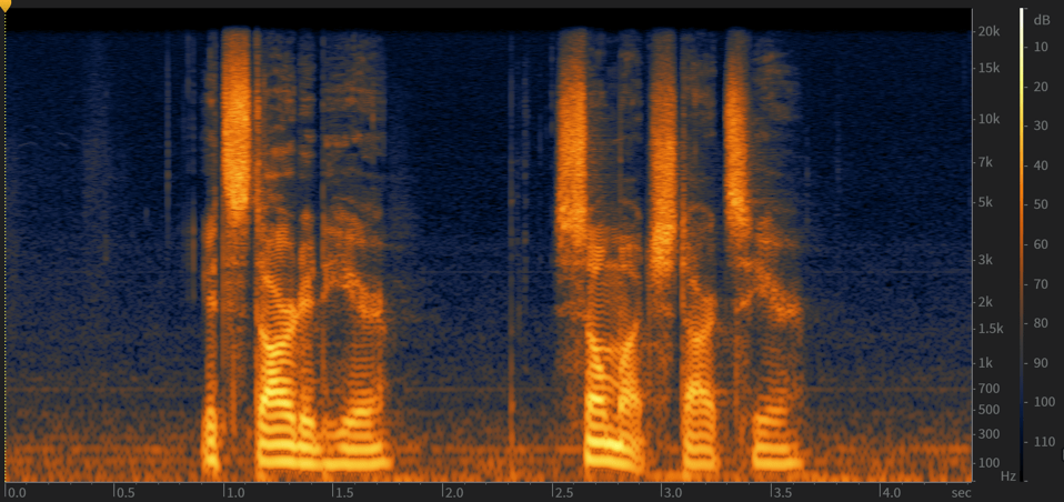
In this example, Louder events (speech) are indicated by brighter colors (yellow/bright orange) and quieter events (breaks in speech and noise floor) are indicated by darker colors (dark orange, blue, black)
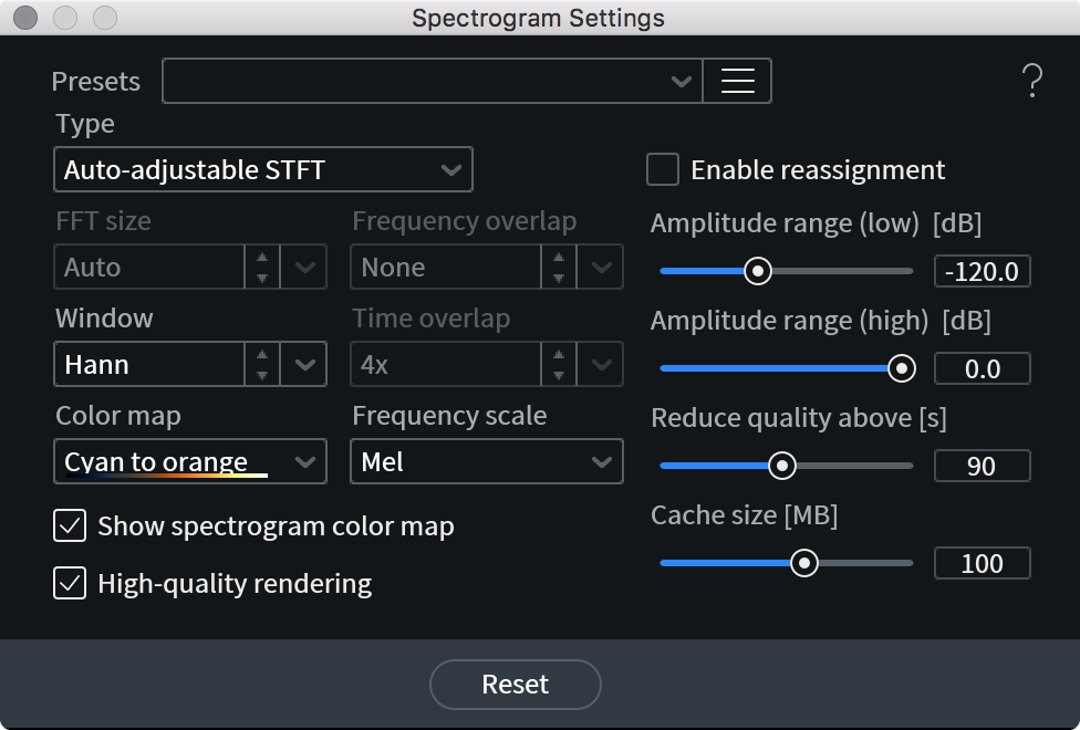
Spectrogram Settings
The RX Spectrogram is highly configurable, you can adjust the default configuration, load a preset or save your own preset in the Spectrogram Settings window.
The Spectrogram Settings window can be opened using the following methods:
- From the “View” menu of the RX Audio Editor
- By right-clicking on the spectrogram display and selecting “Spectrogram Settings” from the context menu
- Using a keyboard shortcut: Command+Shift+, (on Mac) or Ctrl+Shift+, (on Windows)
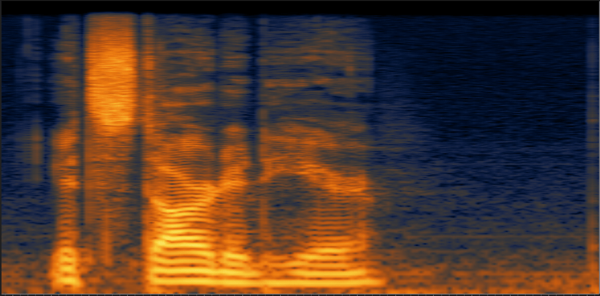
Spectrogram Type
RX offers different methods for displaying time and frequency information in the Spectrogram. RX’s advanced Spectrogram modes allow you to see sharper time (horizontal) and frequency (vertical) resolution simultaneously. There is always a trade-off of display quality versus processing time, so keep in mind that some modes will take longer to draw on the screen than others.
| TYPE | DESCRIPTION | EXAMPLE |
|---|---|---|
| REGULAR STFT | Most common spectrogram type (can be found in other editors) It has a fixed uniform time-frequency resolution. This is the simplest and fastest drawing mode in RX. |
|
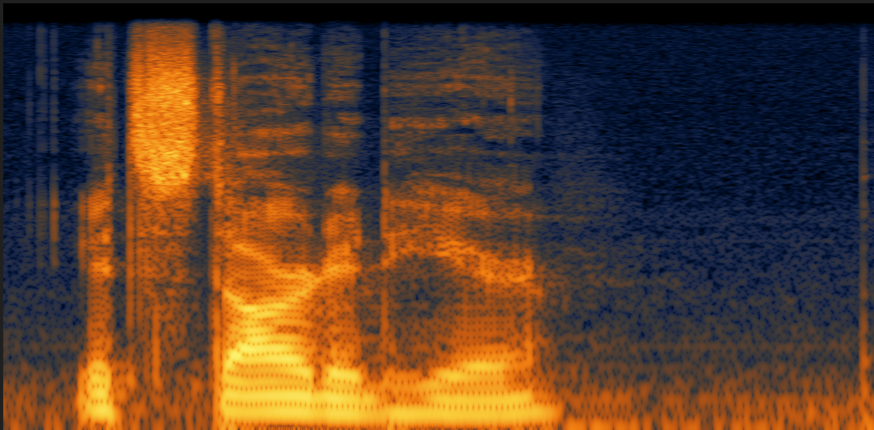
| AUTO-ADJUSTABLE STFT | Automatically adjusts FFT size (i.e. time and frequency resolution of a Spectrogram) according to the zoom level. For example, if you zoom in horizontally (time) you’ll see that percussive sounds and transients will be more clearly defined. When you zoom in vertically (frequency), you’ll see individual musical notes and frequency events will appear more clearly defined. |
|
| MULTI-RESOLUTION | Calculates the Spectrogram with better frequency resolution at low frequencies and better time resolution at high frequencies. This mimics psychoacoustic properties of our perception, allowing the Spectrogram display to show you the most important information clearly. |
|
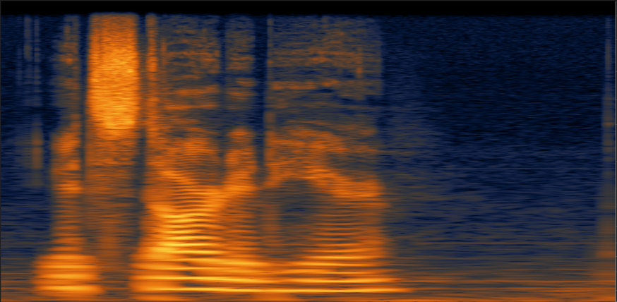
| ADAPTIVELY SPARSE | Automatically varies the time and frequency resolution of the Spectrogram to achieve the best Spectrogram sharpness in every area of the time-frequency plane. This often lets you see the most details for a thorough analysis, but it’s the slowest mode to calculate. |
|
FFT Size
The greater the FFT size, the greater the frequency resolution, i.e. notes and tonal events will be clearer at larger sizes. However, choosing a larger number here will make time events less sharply defined because of the way this type of processing is done. Choosing Auto-adjustable or Multi-resolution modes allows you to get a good combination of frequency and time resolution without having to change this setting as you work.
What does FFT mean?
Fast Fourier Transform: a procedure for the calculation of a signal frequency spectrum. The greater the FFT size, the greater the frequency resolution, i.e., notes and tonal events will be clearer at larger sizes.
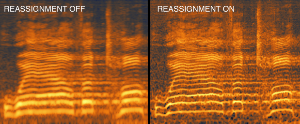
Enable Reassignment
Enables a special technique for Spectrogram calculation that allows very precise pitch tracking for any harmonic components of the signal. When used together with Frequency Overlap/Time Overlap controls, this option can provide virtually unlimited time and frequency resolution simultaneously for signals consisting of tones.
Enable Reassignment Example
Window
Selects between the different weighting functions (or windows) that are used for the FFT analysis. Window functions control the amount of signal leakage between frequency bins of the FFT. “Weak” windows, such as Rectangular, allow a lot of leakage, which may blur your Spectrogram vertically. “Strong” windows, such as Kaiser or cos3, eliminate leakage at the expense of a slight loss of frequency resolution.
Frequency Scale
Using different frequency scales can help you see useful information more easily. Different scales have different characteristics for displaying the vertical (frequency) information in the Spectrogram display.
| Frequency Scale Type | Description |
|---|---|
| LINEAR | Displays frequencies spread out in a uniform way. This is most useful when you want to analyze higher frequencies. |
| LOGARITHMIC | This scale puts more attention on lower frequencies. |
| MEL | the Mel scale (derived from the word Melody) is a frequency scale based on how humans perceive sound. This selection is one of the more intuitive choices because it corresponds to how we hear differences in pitch. |
| BARK | The Bark scale is also based on how we perceive sound, and corresponds to a series of critical bands. |
Frequency Overlap
Controls the amount of oversampling on the frequency scale of Spectrogram. When used together with the Reassignment option, it will increase the resolution of the Spectrogram vertically (by frequency).
Time Overlap
This controls the time oversampling of the Spectrogram. In most cases, overlap of 4x or 8x is a good setting to start with. However, using higher overlap together with the Reassignment option will increase the time resolution of a Spectrogram, letting you see transient events clearly.
Color Map
The Spectrogram display allows you to choose between several different color schemes. There is no right or wrong color setting to use and we recommend you try them all to determine your preference. Sometimes certain color modes will make different types of noise stand out more clearly. Experiment!
High-Quality Rendering
Accurate max-bilinear interpolation of the Spectrogram (recommended). Turning this control off makes Spectrogram rendering slightly faster, but you’ll lose some detail and clarity in the Spectrogram image.
Reduce Quality Above
RX’s Spectrogram uses very accurate rendering, letting you see audio problems, such as clicks, even at low zoom levels. However, performing such rendering for long files can be somewhat slow. When the length of the visible Spectrogram is above the specified number of seconds, the Spectrogram calculation is changed to a fast and less accurate preview mode. When you zoom in, the Spectrogram calculation becomes accurate again.
Cache Size (MB)
Limits the amount of memory used by the Spectrogram.
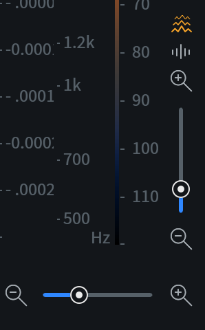
Rulers
On the right side of the Spectrogram/Waveform display are the Amplitude ruler for the Waveform, Frequency ruler for the Spectrogram, and Color Map ruler for the Spectrogram.
Amplitude Rulers
You can right-click on the spectral Amplitude ruler to reveal a selection of amplitude scales:
- dB: Shows Waveform levels in decibels, relative to digital full scale (it is the most common type of scale used for spectrum analyzers).
- NORMALIZED: Shows Waveform levels relative to the full scale level of 1.
- 16 BIT: Shows Waveform levels as quantization steps of a 16-bit audio format (−32768 to +32767).
- PERCENT: Shows Waveform levels as percentage from full scale.
Color Map Ruler
This ruler shows what color represents what amplitude in the Spectrogram. The range of this display is the dynamic range of the RX Spectrogram. You can click and drag the map to change the range and use the scroll wheel to make the range larger or smaller. This is useful for seeing very quiet noises without using gain to change the level of your audio.
Frequency Rulers
Right-clicking on the frequency ruler will display the frequency scale options:
- LINEAR: Linear scale means that Hertz are linearly spaced on a screen.
- MEL (default) & BARK: Mel and Bark are frequency scales commonly found in psychoacoustics, and reflect how our ears detect pitch. They are approximately linear below 500 Hz and approximately logarithmic above 500 Hz.
- MEL scale reflects our perception of pitch: equal subjective pitch increments produce equal increments in screen coordinates.
- BARK scale reflects our subjective loudness perception and energy integration. It is similar to Mel scale, but puts more emphasis on low frequencies.
- MEL scale reflects our perception of pitch: equal subjective pitch increments produce equal increments in screen coordinates.
- LOG: in this mode, different octaves occupy equal screen space. The screen coordinates are proportional to the logarithm of Hertz down to 100 Hz.
- EXTENDED LOG: this extends the logarithmic scale down to 10 Hz, so that it puts even more attention on lower frequencies.
- PIANO ROLL OVERLAY: A representation of how specific frequency ranges correlate to the western musical scale can be displayed by right-clicking on the Frequency ruler and selecting Show Piano Roll. If you would like to hide the frequency indicators so they don’t obscure this piano roll, you can disable Show Frequencies and Ticks (which is enabled by default).
Waveform Displays
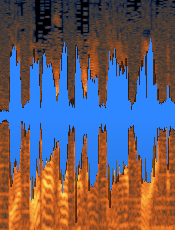
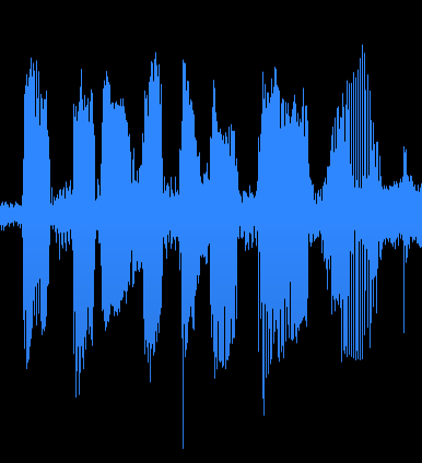
Waveform Transparency Balance Slider

The Spectrogram Display features a transparency slider that lets you superimpose a Waveform display over the Spectrogram, allowing you to see both frequency and overall amplitude at the same time. This can be invaluable for quickly identifying clipping, clicks and pops, and other events.
Below are examples of the same clip shown with different transparency balance values:

Waveform Overview

An overview of the entire audio file’s Waveform is displayed above the main Spectrogram/Waveform display in order to provide a handy reference point when zooming and making audio selections in RX.
The Waveform overview will always display the entire audio file, and will also display any selections made in the main display.
When zooming in on your audio, the currently visible audio region will also be highlighted in the Waveform overview. Click and drag on the highlighted region in order to scroll your main audio display left or right, and click and drag on the edges of the highlighted region in order to make the zoom tighter or wider. To zoom out fully, simply double click on the highlighted visible region.
Note
With your mouse hovering over the Waveform overview, you can also use the mouse wheel to scale the amplitude of the Waveform display to provide a clearer overview. This will not affect the amplitude scaling in the main Spectrogram/Waveform display.
Interactive Tools
Overview
Below the Spectrogram display is a toolbar that includes several options for working with the spectrogram/waveform display. The toolbar is split into three main categories, Navigation, Instant Process, and Selection.

Zoom Tools
You can zoom in horizontally and vertically on both the waveform and spectrogram views.
Zoom Selection Tools
The following zoom selection tools are available in the RX Audio Editor:

- Zoom in: zooms in on the time ruler.
- Zoom out: zooms out on the time ruler.
- Zoom to selection: zooms to fill the spectrogram/waveform display with the current selection.
- Zoom to whole file: resets zoom time and frequency zoom levels to default.
- Zoom tool: When enabled, the zoom level will update to fit the selection to the window when using the Time, Time-Frequency, or Frequency Selection Tools.
Zoom Sliders
Magnitude Ruler Zoom Slider
The vertical slider in the lower right-hand corner of the spectrogram/waveform display controls the zoom level for the spectrogram or waveform amplitude ruler(s). The buttons above the vertical slider select which ruler it will affect when adjusted.
Time Ruler Zoom Slider
The horizontal slider in the lower right-hand corner of the spectrogram/waveform display controls the zoom level of the time ruler.
Navigation Tools
Grab & Drag Tool

When zoomed in on an area, the Grab & Drag Tool [G] can be used to move through the time range by clicking and dragging on the Spectrogram.
Dragging Rulers and Using the Mousewheel
- The rulers to the right and below the Spectrogram display can clicked and dragged to reposition the spectrogram and waveform to show a different time range, amplitude range or frequency range.
- In addition the range shown can be adjusted with your mouse wheel, just place your cursor on top of a ruler and the mouse wheel will adjust the zoom for that ruler.
- To reset any of the rulers to the default display range, double click on the ruler.
Note
- All active selections will be accurately preserved and scaled when zooming the main display.
Channel Selectors
Channel Selectors appear on the left hand side of the spectrogram/waveform display when a file is loaded. Channels can be enabled or disabled individually by clicking on the channel selector buttons. Deselecting a channel will exclude it from playback, selections, and processing.
- If all channels are enabled, single-clicking on a channel selector will disable all other channels, only the channel that was clicked on will remain enabled.
- When some of the channels are disabled, single-clicking on a disabled channel selector will enable that channel without affecting the enabled disabled state of other channels.
- When any channel number of channels are disabled, double-clicking on any channel selector will quickly enable all channels.
Keyboard Shortcuts: Stereo File Channel Selectors
- Select Left Channel Only: Command+Shift+L (Mac); Ctrl+Shift+L (Windows)
- Select Right Channel Only: Command+Shift+R (Mac); Ctrl+Shift+R (Windows)
- Select Both Channels: Command+Shift+B (Mac); Ctrl+Shift+B (Windows)
- These commands only apply to stereo files, they do not apply to files with more than 2 channels.
Channel Order (Multichannel)
When working with multichannel files, the channel selector label order can be configured by right-clicking on the time ruler or by clicking on the arrow to the right of the time format display. The channel order options will update based on the number of channels in the active file tab. The “Discrete” option will label all channels as “M” (mono).
Instant Process
Instant Process [I] is a selection tool modifier. Instant Process is only available in RX Standard and Advanced.

When Instant Process is enabled, any new selection made will be immediately processed with the selected module in the Instant PRocess menu. The module settings applied by instant process reflects the current settings in the selected module.
When Instant Process is disabled, processing, editing and selection tools will function as they normally do.
Note
If you hold Shift while using Instant Process, this will allow you to build up additional selections. Once you release Shift, processing will occur. This is especially useful for tools such as the Magic Wand, which will pick up additional harmonics upon second click. If you don’t like that selection, also hold Alt, and start redrawing a new selection. Release Shift once you’re ready to process.
Instant Process offers several different modes, accessible via a drop down menu, which will instantly process the settings present in the named module/tab. The default settings are used, but if you define custom settings in that module, Instant Process will recognize and apply those custom settings. The modes are:
Instant Process: Attenuate
This mode will instantly apply the active settings from the Spectral Repair module’s Attenuate tab. This is particularly useful if you see anything in the spectrogram you don’t wish to remove entirely, but would rather quickly blend into the surrounding audio to make it less obvious or intrusive.
Instant Process: De-click
Applies the active settings from the De-click or Interpolate modules. De-click Instant Process will automatically remove all clicks present in your selection, which is particularly useful for editing a dialogue file, mismatching sample rate clicks and pops, and vinyl clicks.
If you make a selection under 4000 samples in length, this mode will automatically use the Interpolate module. Selection longer than 4000 samples will use the settings from the De-click module. The De-click module is effective on selections above 4000 samples in size, as it is able to identify clicks in relation to desirable audio, and then intelligently separate and remove the clicks. If a selection is less than 4000 samples in length, it is likely a small selection of an individual click, and Interpolate will fill the selection with audio information based on the surrounding audio.
Instant Process: Fade
This mode will instantly apply the active settings from the Fade module. This is particularly useful if you’d like to smooth over a transition or edit point within a complex audio file, especially if it’s a limited bandwidth selection, such as choosing to fade in a certain harmonic or audio event in an audio file without changing the volume of the rest of the audio.
Instant Process: Gain
This mode will instantly apply the active settings from the Gain module. If you want to quickly adjust certain audio events up or down in volume, you can simply paint over it to see the immediate gain adjustment. For overall volume adjustment, use the Clip Gain line [Cmd+G / Ctrl+G].
Instant Process: Replace
This mode will instantly apply the active settings from the Replace tab in the Spectral Repair module. This is particularly useful if you see anything in the spectrogram you wish to remove entirely, as it will use the audio information that surrounds your selection to instantly and intelligently fill the gap.
Selection tools
The following selection tools are available in the RX Audio Editor:
| Icon | Name | Description |
|---|---|---|

|
Time selection tool [T] | Select a range of time within the file (horizontally within the spectrogram) |

|
Time-Frequency Selection tool [R] | Makes rectangular selections in the spectrogram display to isolate sounds by time and frequency |

|
Frequency Selection tool [F] | Makes frequency only selection (vertical in spectrogram) |

|
Lasso Selection tool [L] | Makes a selection based on a free-form outline drawn with your cursor on the spectrogram |

|
Brush Selection tool [B] | Draw a free-form selection using a defined brush size in time and frequency in RX’s spectrogram. The size of the Brush Selection tool can be adjusted by clicking and holding on the Brush Tool icon. Note With the brush tool selected, you can also hold Control/Command and move the mouse wheel to make the brush size larger or smaller. |

|
Magic Wand Selection tool [W] | Automatically selects similar harmonic content surrounding the selected material. Click on the spectrogram to select the most prominent tone under the cursor when the magic wand is selected. Clicking on an existing selection with the Magic Wand tool will automatically select the overtone harmonics or related audio components of your current audio selection. Note You can use the Brush or Lasso tools first to broadly define a sound and then use Magic Wand to refine your selection to include relevant harmonic material. |

|
Harmonic Selection tool [Shift+Cmd+H / Shift+Ctrl+H] | Duplicates your current selection to include harmonics above it. Start by selecting the fundamental frequency of audio with harmonics, then add or remove harmonic selections with this tool before processing. |
View Clip Gain
Quickly enable/disable the clip gain curve overlay.

Selection Modifiers
[Shift] - Add to selection
Hold down shift after making a selection in order to add another, separate selection. If any part of the new selection overlaps any other, the selections will be grouped into one.
Use Shift to combine different selection types:
This can be especially powerful when combining several selection tools to create multiple selections of different size and shape.
Multiple selections made using the Shift modifier key with different selection tools
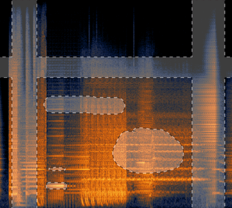
[Alt/Option] - Subtract from Selection
Holding down Alt/Option will allow you use the currently chosen selection tool to remove or erase any portion of an existing audio selection. This can be especially useful with the Lasso or Brush tools, allowing you to edit or refine any piece of an existing selection.
This is also useful for refining complicated free-form selections. First make your lasso, brush, or magic wand selection, and then hold alt while using the time, frequency, or time and frequency tools to exclude entire time and frequency ranges from processing.
Use Alt/Option modifier to remove from the active selection:
Holding Alt/Option effectively turns the Brush tool into a selection eraser for broad refinements and Lasso into a selection “X-Acto knife” for detailed selection revision.
Selections refined to perfection using the Alt key modifier
Linking Selection State to Undo History Events
Using Ctrl/Cmd-Z to undo any particular process will also bring back the previous audio selection exactly as it was before applying any processing. In order to make use of this feature, be sure that Store Selections with Undo History is enabled inside of RX’s Preferences > Misc menu.
[Ctrl/Cmd] - Move Playhead without affecting Selection state
Hold down Ctrl/Cmd to move the transport’s playhead to any position without erasing your current audio selections. This can be especially useful with previewing or comparing complex audio selections without having to remake these specific audio selections.
[Mouse Over] - Grab and Drag Selection
After using any of RX’s tools to select a portion of your audio, when the mouse is subsequently placed on top of any selection, a Grab and Drag hand cursor will be displayed automatically, allowing you to change the position of that selection.
Undo History
Overview
In addition to the Edit > Undo and Edit > Redo commands, the Undo History list allows you to see a timeline of changes you’ve made and non-destructively revert back to earlier states. RX keeps a log of all your edits in this Undo History.
When modifying Clip Gain or processing with the Module Chain related edits will be added under parent items, named “Clip Gain” and “Module Chain” respectively, in the Undo History list.

Note
You can rename items in the undo history by double-clicking them. You can save an .rxdoc of your current file to retain the undo history list, you can find more information on RX documents in the Working with Files chapter.
Export History
You can use the Export History feature to save an XML file, listing the entire undo history for your particular file.
For forensic and archival purposes, it is often useful to have an official record of all edits that were made to a particular file. When a file’s history is exported, the following information will be stored in an XML file:
- RX Version Number
- Time and Date
- Corrected File
- Number of Channels
- Sampling Rate/Bit Depth
- Edit History: Parameters and Selections
Application Menus

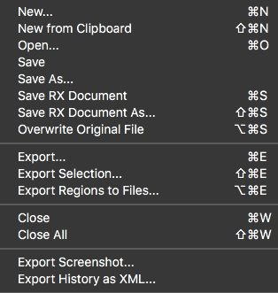
File
The file menu provides options for creating, importing and exporting files. For information about file management in the RX Audio Editor, see the Working with Files chapter.
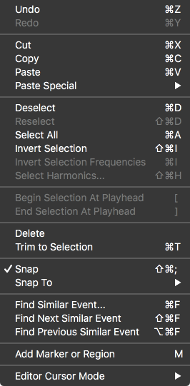
Edit
The Edit menu includes the following options:
- Undo [Ctrl/Cmd-Z] Reverses the last action taken.
- Redo [Ctrl/Cmd-Shift-Z; Ctrl/Cmd-Y] Cancels the undo.
Undo History
- The RX Audio Editor includes an Undo History event list in each file tab. The Undo History list stores a list of all processing or edit operations applied to a given file.
- Cut[Ctrl/Cmd-X] Removes the currently selected audio and stores it temporarily on the Clipboard.
- Copy [Ctrl/Cmd-C] Makes a copy of the currently selected audio and places it on the Clipboard.
- Paste[Ctrl/Cmd-V] Places audio that has been copied or cut to the Clipboard at the current cursor point.
- Paste Special Provides additional options for placing the Clipboard data:
- Insert [Ctrl/Cmd-Alt/Opt-V]: Inserts the audio from the Clipboard and moves audio in the project [does not overwrite]
- Replace [Ctrl/Cmd-Alt/Opt-Shift-V]: Replaces audio in the project with audio from the Clipboard
- Mix [Shift-V] Combines the audio from the Clipboard with audio in the project
- Invert and Mix [Alt/Opt-V] Inverts the audio in the Clipboard and then mixes it with audio in the project. This is useful when you want to compute the difference between two signals.
- To Selection [Alt/Opt-Shift-V] Pastes audio from the clipboard only within the selection bounds, regardless of the copied audio’s length. If the copied audio is longer than the new selection, the audio will be cropped to fit. If the selection is longer than the audio being pasted, silence will be inserted to fill the remaining space.
- To Clip Gain Only [Ctrl/Cmd-Shift-V] Pastes only clip gain information to the current selection
- Insert [Ctrl/Cmd-Alt/Opt-V]: Inserts the audio from the Clipboard and moves audio in the project [does not overwrite]
- Deselect [Ctrl/Cmd-D] If audio is selected, deselects it and places the anchor sample at the start of the selection.
- Reselect [Esc] Restores the last selection if you have no current selection.
- Select All [Ctrl/Cmd-Shift-D] Selects the entire open file.
- Invert Selection [Ctrl/Cmd-Shift-I] Selects everything that isn’t currently selected.
- Invert Selection Frequencies [Ctrl/Cmd-I] Selects everything in the current time range that isn’t selected. This is useful for refining processing by first selecting what you don’t want to process, then inverting the selection frequency.
- Select Harmonics [Ctrl/Cmd-Shift-H] Refines the current selection to include more harmonics. For this feature to work well, try it with a simple selection that includes only the fundamental harmonic of what you are trying to select. You can also use the Magic Wand tool to automatically refine a selection to include the appropriate harmonics.
- Begin Selection at Playhead [Left Bracket] during playback only If audio is currently selected, this will automatically adjust the selection to begin at the current playback position.
- End Selection at Playhead [Right Bracket] during playback only Automatically create a selection between the current playhead position and the original anchor playhead position.
- Delete Selection [Delete on a time selection] Deletes the selected audio and closes the space with audio from either side of the timeline.
- Silence [Delete on a frequency, time-frequency, or freeform selection] Deletes selected audio and replaces it with silence.
- Trim to Selection [Ctrl/Cmd-T] Deletes all audio except for the selected audio.
- Add Marker or Region [M] This will create a new marker point at the current location of the cursor/playhead or create a new region if any audio is selected.
- Edit Cursor Mode Changes the behavior of the editor cursor to select by time and/or frequency, or to zoom. These modes can also be selected from the Cursor Mode buttons.
- Select Time [T] Makes a time selection
- Select Time/Freq [R] Makes a Rectangular time-frequency selection
- Select Freq [F] Makes a frequency selection for the duration of a file
- Lasso [L] Selects everything in a freely defined area
- Selection Brush [B] Selects everything in a predefined radius
- Selection Wand [W] Intelligently selects material similar to whatever is under your cursor [magic wand]
- Zoom Time [Z] Zooms in time
- Zoom Time/Freq [Shift-Z] Zooms in time and frequency
- Zoom Freq [Alt/Opt-Z] Zooms in frequency
- Grab Time [G] Grabs and drags the view in time
- Grab Time/Freq [Shift-G] Grabs and drags the view in time and frequency
- Grab Freq [Alt/Opt-G] Grabs and drags the view in frequency
- Select Time [T] Makes a time selection
- Snap [Ctrl/Cmd-Shift-;] Snap selections to the boundaries selected in the “Snap To” sub-menu.
- Snap to:
- Markers
- Ruler Coarse
- Ruler Fine
- Zero Crossings
- All
- None
- Markers
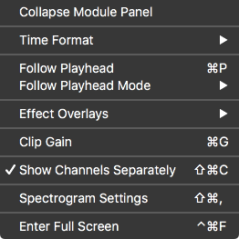
View
The View menu includes the following options:
- Collapse/Expand Module Panel Collapses the module list panel of RX into a row of icons.
- Time Format RX’s time scale and playhead location counter can be set to show different time units. Learn more about changing the time format in the Transport chapter
- Follow Playhead [Ctrl/Cmd+P]: Toggles whether or not the current view follows the playhead position during playback.
- In Page mode, the view will follow the playhead one view length at a time.
- In Continuous mode, the view is centered on the playhead as it moves across the file.
- In Page mode, the view will follow the playhead one view length at a time.
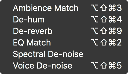
- Effect Overlays: This sub-menu allows you to turn special display features for the De-clip and Spectral Repair modules on and off.For an overlay to be visible, you need to have the option selected in the view menu, and the corresponding module window needs to be open.
- De-clip Threshold When the waveform is visible, the threshold settings and controls appear as white lines within the display. This display can be used to adjust the de-clip threshold settings.
- Spectral Repair Source Regions Displays effective region bounds when using the Spectral Repair module.
- De-clip Threshold When the waveform is visible, the threshold settings and controls appear as white lines within the display. This display can be used to adjust the de-clip threshold settings.
- Clip Gain: Enables/disables the Clip Gain envelope in the main editor window. The Clip Gain curve can also be toggled on or off by clicking the “View Clip Gain” button to the right of the selection tool buttons, or by using the following keyboard shortcuts: Command+G (Mac); Ctrl+G (Windows).
- Show Channels Separately: Toggles how channels are displayed in the spectrogram/waveform view. When enabled, each channel will be drawn in its own lane in the main editor view. When disabled, the channels are drawn in one summed view. This allows for greater vertical resolution, especially when working with multichannel files. This option can also be toggled on or off by: clicking the Channel View button to the left of the mini waveform overview display or by using the following keyboard shortcuts: Command+Shift+C (Mac); Ctrl+Shift+C (Windows).
- Spectrogram Settings: Opens the Spectrogram Settings window.
- Enter full screen: Enables full screen mode.
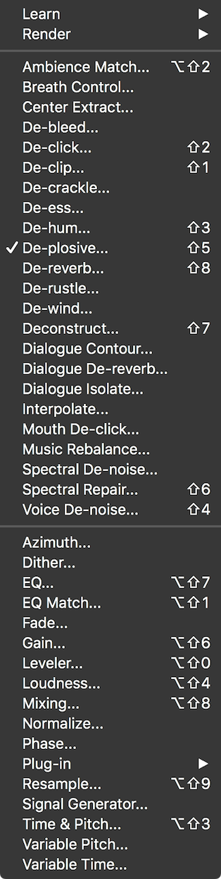
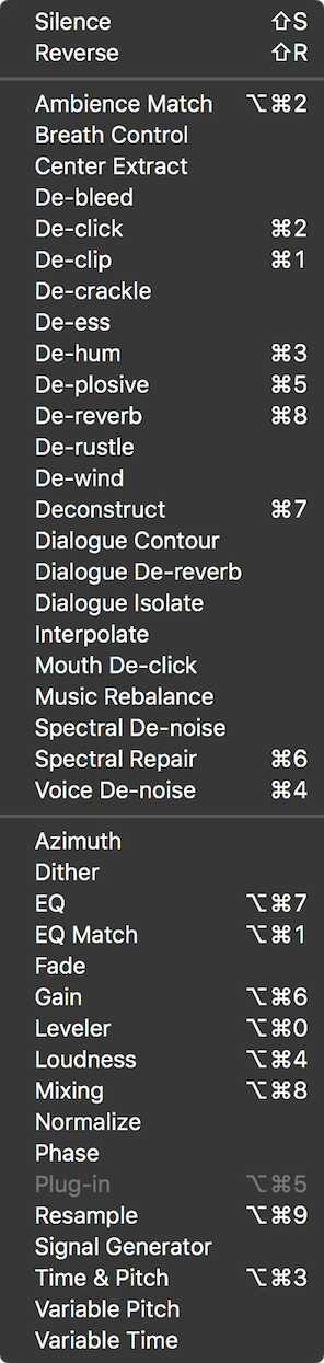
Modules
The Modules menu includes options for opening module windows, running Learn on the current selection without opening the module window, and rendering module settings on the current selection without opening the module window.
Open Module Window
Open a module window by selecting it from this menu.
Learn
Run a Learn pass on the current selection without opening the associated module window.
Render
Render settings for any module on the current selection without opening the associated module window.
Transport
The Transport menu includes the following options:
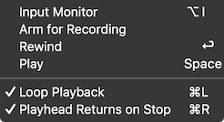
- Input Monitor [Alt/Option-I] Enables input monitoring. When input monitoring is enabled, the input signal of RX will be routed to the output signal of RX.
- Arm for Recording / Record / Stop Recording [Alt/Option-Space] Runs the next possible step for recording. If you have not opened a new file, Arm for Recording will open the New File dialogue box for you.
- Rewind [Return] Sets the playhead to the beginning of the file.
- Play/Stop [Space] Starts or stops playback. If Input Monitoring is enabled, starting playback will temporarily suspend Input Monitoring.
- Loop Playback [Control/Command-L] Toggles playback looping. If nothing in the file is selected, the end of the file will loop back to the beginning.
- Playhead Follows Playback [Control/Command-R]: Toggles the behavior of the playhead on stop. If this is enabled, the playhead will return to the anchor sample (the position before playback began).
- This is useful for comparing processing. If this is disabled, the anchor sample will be set to the current playhead position. This is useful for moving through a file while listening for irregularities.
- This is useful for comparing processing. If this is disabled, the anchor sample will be set to the current playhead position. This is useful for moving through a file while listening for irregularities.
Window
The Window menu includes the following options:
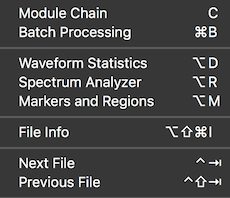
- Batch Processing [Ctrl/Cmd+B]: This gives you access to file based batch processing, as explained in the Batch Processor chapter.
- Waveform Statistics [Alt/Opt+D]: This gives you access to informational readouts on a variety of amplitude measurements, as explained in the Waveform Statistics chapter.
- Spectrum Analyzer: The Spectrum Analyzer displays an analytical view of your audio. More information is located in the Spectrum Analyzer chapter.
- Markers and Regions [Alt+M]: Markers and regions allows you to define and save particular points or selections in time for your audio file. More information is located in the Markers and Regions
- Close All Floating Windows/Reopen Closed Windows [Ctrl/Cmd+Opt+W]: Closes or reopens all floating windows.
- File Info: View metadata and other information about the audio file, as explained in the Working with Files chapter.
- Next File (Control-Tab) Changes RX’s current file tab to the next file in the window order.
- Previous File (Control-Shift-Tab) Changes RX’s current file tab to the previous file in the window order.
Help
The Help menu includes options for launching the product documentation, viewing the Keyboard Shortcut Guide, and accessing tutorial videos online.
Preferences
Audio
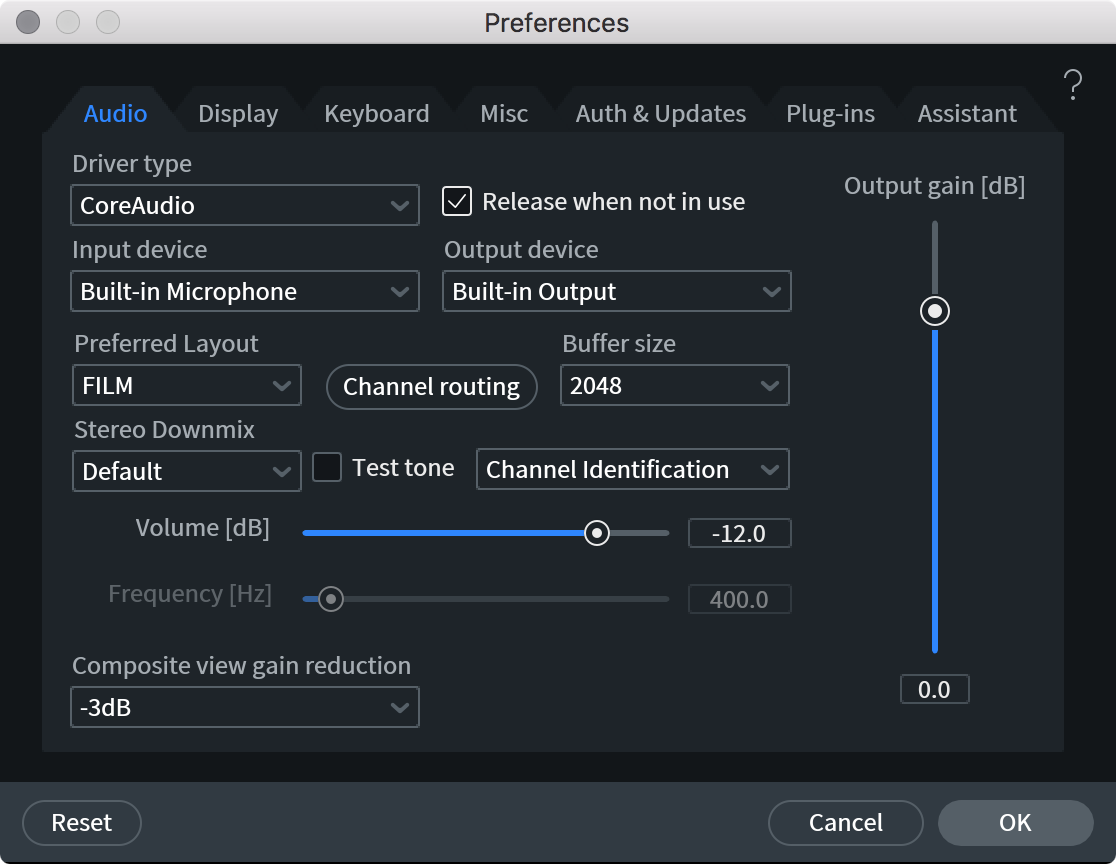
- Driver Type: Selects the audio device driver type (for example: ASIO, CoreAudio, or RX Monitor)
Note
- Some hardware devices monopolize the audio drivers when sending audio clips to RX via RX Connect. If you are not able to hear the audio sent to RX from your DAW with RX Connect, change the audio driver to RX Monitor in the Driver type menu.
- Some hardware devices monopolize the audio drivers when sending audio clips to RX via RX Connect. If you are not able to hear the audio sent to RX from your DAW with RX Connect, change the audio driver to RX Monitor in the Driver type menu.
- Input/Output Device: Choose the device/sound card you want RX to use for playback and recording.
- Buffer Size: The total playback buffer size. In general, lowering these buffer sizes will improve meter responsiveness and lower latency, but increase CPU needs. Raising buffer sizes will lower CPU cost but increase latency. It’s worth exploring these ranges to find values that work best on your system.
- Num Buffers: Number of playback sub-buffers. (Windows MME Only.)
- Composite View gain reduction: Nondestructively reduces the output gain of all clips included in the Composite View tab by the amount specified in the dropdown.
- Channel Routing: Opens the Channel Routing window. Input and output channel routing can be configured in this dialog when working with ASIO/CoreAudio driver types or to configure multichannel output routing.

- Preferred Layout (Multichannel only): Selects the default channel ordering option when multichannel files are loaded in the application. (Advanced only)
- Stereo Downmix (Multichannel only): Selects the stereo downmix configuration to use when monitoring multichannel files with a stereo audio output device. (Advanced only)
Downmix note
- RX does not support downmixing or upmixing files when saving or exporting. The downmix option only applies to playback of multichannel files on stereo systems.
- RX does not support downmixing or upmixing files when saving or exporting. The downmix option only applies to playback of multichannel files on stereo systems.
- Configure Driver: Launches the manufacturer’s driver configuration dialog.
- Release when not in use: Auto-closes the audio device when playback in RX stops, freeing it for use in other audio applications. Disable this if playback from RX isn’t responsive enough.
- Test Tone: The test tone generator is useful for testing your speakers, audio hardware and listening environment. Tones at set frequencies or at a custom frequency can be used as test tones, as can white or pink noise. In addition, a Channel Identification mode will identify left and right speakers.
- Enable: Starts playback of a test tone.
- Type: Sets the type of test tone to play.
- Volume: Sets the volume of the test tone.
- Frequency: Sets the frequency of the test tone.
- Enable: Starts playback of a test tone.
- Output Gain: Output gain allows you to nondestructively adjust the playback level of RX 7 Audio Editor.
Display
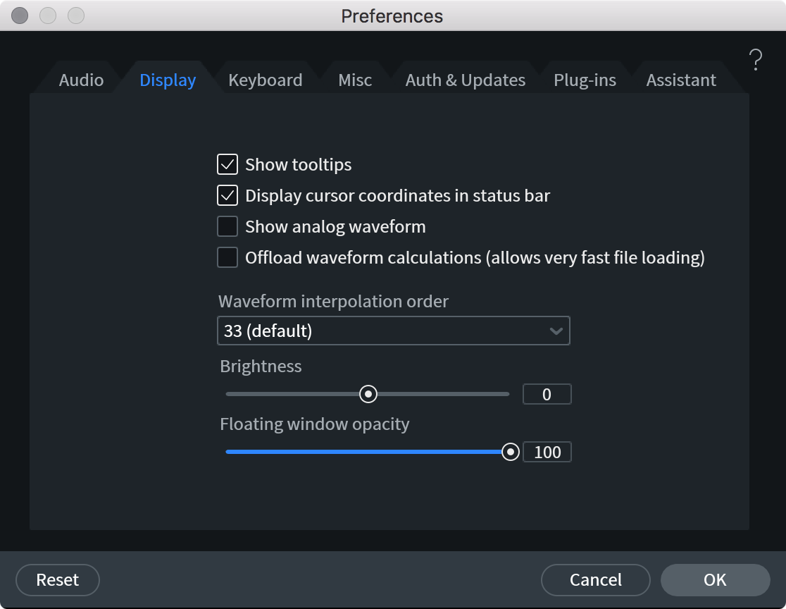
- Show tooltips: When enabled, hovering over an RX feature with the mouse cursor will show a short description of the feature.
- Display cursor coordinates in status bar: When enabled, the time coordinate of the cursor is shown in the status bar at the bottom of the RX main window. The amplitude of the audio at the cursor position and the frequency at the cursor position is also shown.
- Show analog waveform: When digital audio is played back, it is converted to analog. The peak values in the analog waveform can be larger than the peaks in the digital waveform, leading to clipping in the output of a digital-to-analog converter. When Show analog waveform is enabled, RX will compute an analog waveform in the background. Any peaks will be highlighted in red on top of the existing digital waveform.
Note
- RX will automatically display an analog waveform when zooming in at extreme zoom levels.
- RX will automatically display an analog waveform when zooming in at extreme zoom levels.
- Offload waveform calculations: When enabled, RX’s waveform display will be computed in the background. This allows very large files to be loaded very quickly, but it slows down RX’s waveform displays.
- Waveform interpolation order: If you zoom into the waveform so that individual samples become visible, RX will display an upsampled analog waveform as well as the individual digital samples. The interpolation order controls the quality of upsampling. Higher values yield more accurate analog waveforms at the expense of CPU usage.
- Brightness: Adjusts the general brightness of the RX interface, allowing you to make RX more readable on your specific display.
- Floating window opacity: Changes the opacity for RX’s floating windows. This can be useful if you wish to leave floating windows on top of the spectrogram and waveform without completely obscuring the display.
Keyboard
Customizing Keyboard Shortcuts
While RX includes default keyboard shortcuts, you can also customize them to your liking.
Refer to the Keyboard Shortcut Guide to reference a list of default key commands and internal shortcut command names used by RX. Referring to the guide can help you quickly identify the name of the key commands you want to customize and search for them in the “Show commands containing” field (explained below.)
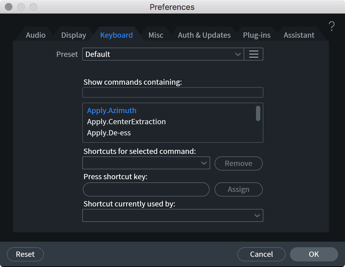
- Presets: Save groups of key assignments with this tool.
- Show commands containing: Lets you search by keyword for a command you want to assign to a keystroke.
- Shortcuts for selected command: Shows if there are any keystrokes assigned to the command selected in the above menu.
- Remove: Removes the currently assigned keystroke from a command.
- Press Shortcut Key: To assign a new keystroke to a command, select the command from the menu, then click in this field and press a key or combination of keys.
- Assign: Assigns the entered keystroke to the current command. The shortcut will only be assigned to the current command if you press this button.
- Shortcut key currently used by: Lists commands that the current keystroke is assigned to.
Using the Alt modifier on Windows
On Windows systems, by default, “Alt + a letter” will open the corresponding menu for your currently open application. Alt + V for example will open RX’s View menu drop down. By default, none of RX’s shortcuts should conflict with these keyboard shortcuts, however if you wish to assign Alt + V to another operation, it will take precedence over the View menu.
Misc
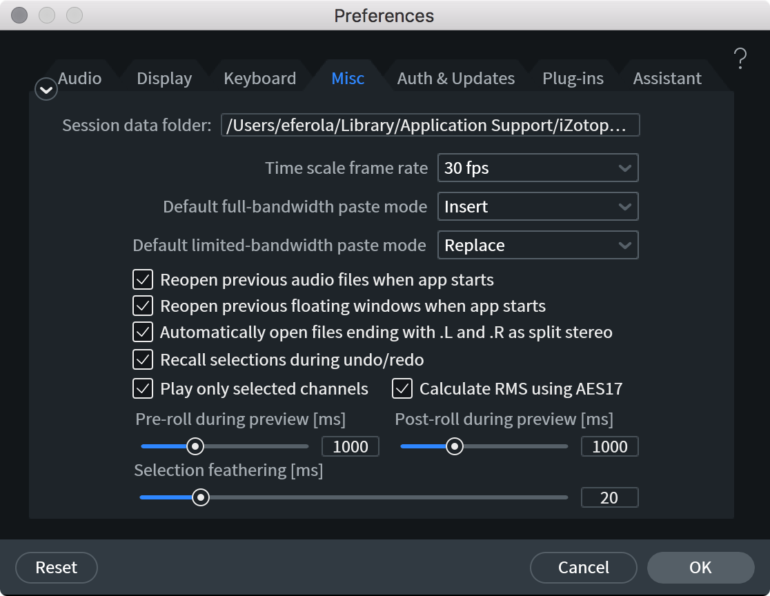
- Session data folder: Allows you to choose a different folder to save RX’s temporary session data. These files are created to allow actions to be undone and sessions to be recalled in RX. Because these can be very large, it is best to set this to the drive on your computer with the most free space.
- Time scale frame rate: This sets the frame rate used to draw the time scale when RX is set to display the time code (see View menu or right-click the time ruler to change this setting). Choose from a list of standard frame rates or click in the combo box to define a custom frame rate.
- Default full-bandwidth paste mode: This controls RX’s behavior when pasting a full-bandwidth audio selection. Insert will move aside existing audio, Replace will overwrite existing audio, and Mix will add to existing audio.
- Default limited-bandwidth paste mode: Similar to the full-bandwidth paste mode, this controls RX’s behavior when pasting a limited-bandwidth audio selected.
- Reopen previous audio files when app starts: When enabled, RX will open all of the files (including edits, processing and undo history events) that were present when RX was last closed. Disabling this option will open the RX Audio Editor in its default state (no files loaded.)
- Reopen previous floating windows when app starts: When enabled, any floating windows that are open when the application is closed will be reopened the next time the application is opened.
- Automatically open files ending with .L and .R as split stereo: Mono audio files with (.L and .R) as well as (.1 and .2) extensions will be opened as stereo files when this option is enabled.
- Recall selections during undo/redo: When this is enabled, RX will recall the selection used for an item in the undo history. When stepping through the undo history events, selections that were used for each event will be restored along with the audio.
Disabling the selection undo/redo option
- Sometimes it is useful to turn this off if you need to compare undo history items and not break your current selection (like a useful loop).
- Sometimes it is useful to turn this off if you need to compare undo history items and not break your current selection (like a useful loop).
- Play only selected channels: If only a single channel of audio is selected and this option is enabled, all other channels will be muted during playback.
- Calculate RMS using AES-17: Uses the AES-17 1998 standard for RMS calculations (0 dB is a full scale sine wave) in the level meter, Waveform Statistics and Leveler modules. The other option is when 0 dB is the RMS of a full-scale square wave. These options differ by 3 dB.
- Pre- and Post-Roll during preview (ms): When Previewing audio processing in any module, the specified time amount will be added to the beginning and end of the previewed selection in order to provide contrast between unprocessed and preview-processed audio.
- Selection Feathering (ms): Allows for crossfading of processed and unprocessed audio when processing. If you need to make more precise edits, set this to 0.
Auth & Updates
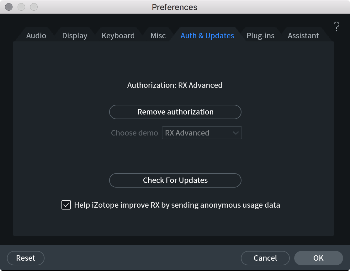
Provides options to authorize or de-authorize RX (explained in the Authorization chapter), launch the iZotope Updater and choose how often the Updater automatically checks for updates.
Plug-ins
RX 7 Audio Editor supports the use of the following plug-in formats in the “Plug-in” module:
- VST 2: Windows and Mac
- AU (AudioUnit): Mac Only
- DirectX: Windows only
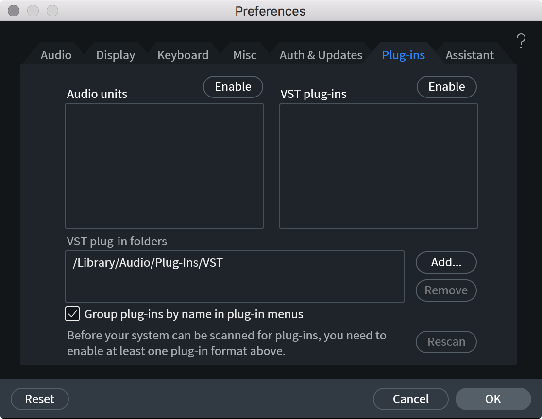
- Plug-in Lists: Displays plug-ins that have been scanned for use in the “Plug-in” hosting module of the RX Editor.
- Enable: Enables that plug-in format for use in the RX Audio Editor. This will trigger plug-in scanning to begin in the background.
Disable: Disables the associated plug-in format. This will clear the scanned plug-in list for that format. Re-enabling that plug-in format will prompt RX to re-scan that plug-in format.
Note
- If a plug-in failed scanning for any reason, the plug-in’s name will be prefixed with an error tag (ex: [Crashed] or [Failed]) to help troubleshoot the failure
- If a plug-in failed scanning for any reason, the plug-in’s name will be prefixed with an error tag (ex: [Crashed] or [Failed]) to help troubleshoot the failure
VST plug-in folders: Allows you to add or remove custom VST2 plug-in folder paths. RX uses the system VST2 plug-in folder by default. If you are using a custom directory for VST2 plug-ins, use this option to ensure that those VST2 plug-ins will be scanned.
Note about sub-folders when scanning for plug-ins
- RX will scan the first level of sub-folders in the custom VST2 folder. If some of your plug-ins do not show up when you scan them, and you know they’re in a subfolder of your plug-in folder, try moving them up one directory level.
- RX will scan the first level of sub-folders in the custom VST2 folder. If some of your plug-ins do not show up when you scan them, and you know they’re in a subfolder of your plug-in folder, try moving them up one directory level.
Group plug-ins by name in plug-in menus: When enabled, the RX plug-in menu will group plug-ins by common first words, usually the manufacturer’s name. When disabled, the RX plug-in menu will appear as a single, alphabetically sorted list.
Rescan: If RX detects that a plug-in is unstable, it will blacklist it and prevent it from being opened. The rescan option allows you to clear the blacklist of unsupported plug-ins and rescan all installed plug-ins in case an RX update or an update from the plug-in manufacturer resolves the issue.
Assistant
Bypass Repair Assistant analysis and processing suggestions for: Informs what common audio problems will be considered when Repair Assistant analyzes a selection. When an option is checked in this list, the associated audio problem will be excluded from analysis and processing suggestions. Options include: Clipping, Clicks, Hum, and Noise.
Composite View [STD & ADV]
Overview
The Composite View feature in the RX Audio Editor combines all active tabs into one “Composite” tab that allows you to apply the same processing to multiple files simultaneously. Composite View can be a valuable tool for increasing efficiency when performing repetitive spectral editing functions.
Workflow
To enter Composite View mode, click on the Enter Composite View button.

When you are done making changes in Composite View, click on the Exit Composite View button to continue working with your individual tracks.

Important Notes
- Composite View is designed to function as a bulk editor, it is not intended for mixing. A maximum of 16 files can be collapsed into a Composite view tab.
- Composite View assumes that all files start at the same point
Use the Signal Generator module to Insert silence
- If needed, you can adjust file start times by inserting Silence with the Signal Generator or using edit commands to modify timing before collapsing your files into a Composite View tab.
- If needed, you can adjust file start times by inserting Silence with the Signal Generator or using edit commands to modify timing before collapsing your files into a Composite View tab.
- Sample Rates: Composite View requires all files to have matching sample rates.
Resample files using the Resample module
- Use the Resample module to conform each file tab to the same sample rate value
- Use the Resample module to conform each file tab to the same sample rate value
- Spectrogram Display: Composite View displays a summed composite spectrogram/waveform display for all files collapsed into the Composite tab. To view individual file displays, simply exit Composite View.
- Editing and Processing: All processing and edits applied in Composite View will be applied to all tracks.
- Undo: To revert edits made in Composite View on a subset of tracks you can exit composite view and use the Undo History list to undo changes made to individual files.
- Playback: Composite View plays back the sum of all files included in the Composite tab.
- Channel selection states in individual tabs are not respected in Composite View playback or processing.
- Channel selection states in individual tabs are not respected in Composite View playback or processing.
- Markers and Regions are not supported in Composite View.
- Compare Settings functionality is not supported in Composite View.
- De-bleed is not recommended for use in Composite View.
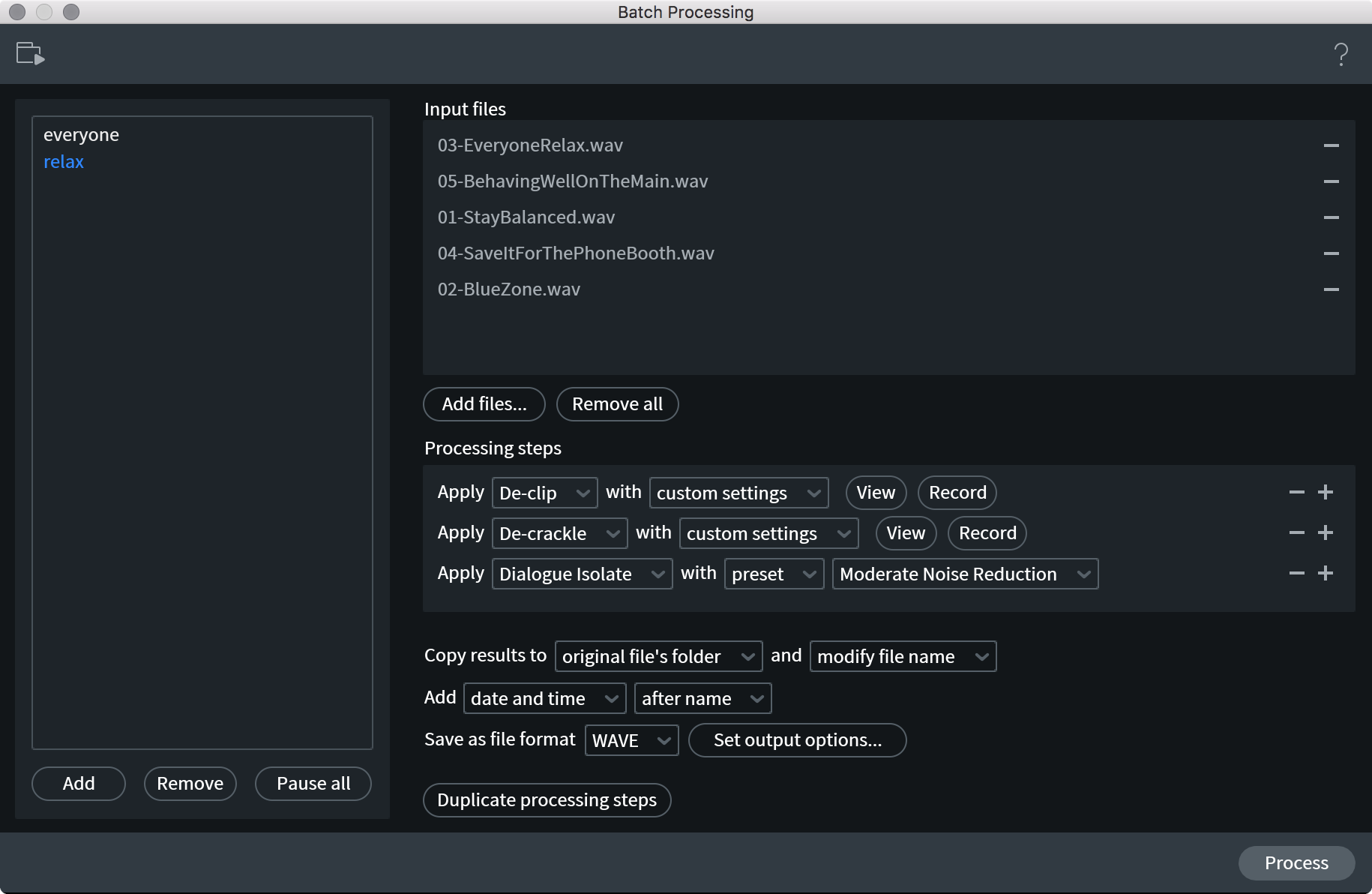
Batch Processing
Overview
The Batch Processing window allows for the creation of custom batch processing jobs, streamlining the time-consuming task of applying the same processing steps to multiple files. Several Batch Processing jobs can be queued simultaneously and run in the background, allowing the RX Audio Editor to be used for other tasks while the Batch Processing jobs are running.
The Batch Processing window can be opened using the following methods:
- Navigate to the RX Audio Editor “Window” menu and select “Batch Processing“
- Open the Batch Processing window using the default keyboard shortcuts: Command+B (Mac); Ctrl+B (Windows)
Batch Processing Job List
The Batch Processing job list provides options for adding, renaming, removing, and pausing batch processing jobs.
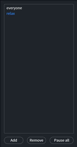
Add
Creates a new batch processing job and adds it to the bottom of the list.

Rename
Batch processing job names can be customized. Double-click on the job name you would like to rename, enter the new name in the text edit box and use the Enter or Return key to update the name.
Remove
You can delete a job from the list by selecting it and clicking the Remove button.

Pause All
Batch processing jobs can be run in parallel. All active jobs can be paused by clicking the Pause all button below the batch processing job list.

Input Files
The Input Files panel allows for files to be added or removed from the selected batch processing job.
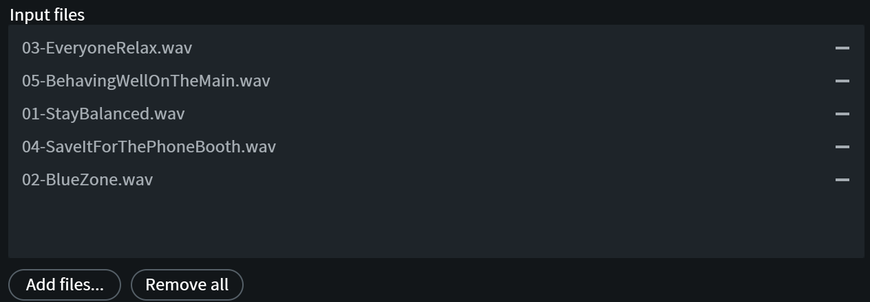
Add Files
Files can be added to the currently selected batch processing job by using one of the following methods:
- Click the Add files… button at the below the Input files panel.

- Drag and drop files from Finder (Mac) or Windows Explorer (Windows) into the Input files panel of the Batch Processing window.
Tip
Add multiple files from the same folder by holding the Command key (Mac) or ctrl key (Windows) when selecting files from the Finder or Windows Explorer dialog.
Remove files
Files can be removed from the currently selected processing job by clicking the “-” button to the right of the file name in the Input Files list.

Processing Steps
The processing step panel includes options for adding, removing, and customizing the processing steps for the currently selected batch processing job.
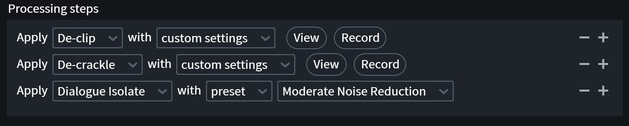
Add Steps
Click the + button to add a new step to the processing chain.
Remove Steps
Click the - button to remove the associated processing step from the processing chain.
Customize Settings
Each processing step includes options for selecting the module to process with and configuring the associated settings.

Module Selection Menu
Select the module to process with in the leftmost dropdown menu.
Custom Settings/Preset
Select the source for the module settings:
Custom settings: When selected, will allow for settings to be based on the current settings in the associated module window. When custom settings is selected, the “View” and “Record” buttons will be displayed. Settings must be recorded in order to apply processing.
- View: Opens the selected module window.
- Record: Captures the current settings in the selected module to use when processing the associated step.
Preset: When selected, the settings will be based on the preset chosen in the dropdown menu that appears to the right of the custom settings/preset menu.
Output Options Panel
This panel includes options for determining the expected location of the processed files, modifying file names, and configuring output file formats for the selected batch processing job.
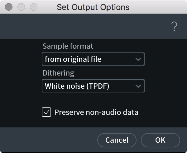
File Location
Options include:
- Original file’s folder: copy processed files to the same directory as the original file.
- Choose folder…: Select the destination for the processed files from the system dialog that appears.
File Naming
- Modify file name: When selected, options for configuring the modified file name will appear below.
- Add Date/Time to the beginning or end of the file name.
- Add custom text to the beginning or end of the file name.
- Add Date/Time to the beginning or end of the file name.
- Keep same file name
File Format
Choose the output file format and configure the options associated with the selected file format (e.g. bit rate, quality, etc…).
Available File Formats:
- WAVE
- Broadcast Wave (BWF)
- AIFF
- FLAC
- Ogg Vorbis
- mp3
The file format options can be configured by clicking the “Set Output Options…” button.
Duplicate Processing Steps
Creates a new job with the same processing steps used in the currently selected batch processing job.
Note
Input files from the original job are not copied over to the duplicated batch processing job.
Repair Assistant
Overview
Repair Assistant is designed to detect common audio problems in a selection and provide three processing chains tailored to solving the problems detected during analysis.
Repair Assistant is available in the RX Audio Editor. To begin using Repair Assistant, make a selection in the active file tab and click the Repair Assistant button in the upper right hand corner of the RX Audio Editor window.

Repair Assistant Selections
Repair Assistant was designed to detect problems in full frequency bandwidth selections. Even if a frequency band limited selection is made when starting analysis (e.g. brush tool selection), a full frequency bandwidth version of the current selection will be used during analysis. The current selection will be maintained after running Repair Assistant.
Source Type Selection
The first Repair Assistant screen includes source type selection options. This affects the type of processing chains generated and is used in analysis to measure noise amounts and determine processing chain components and settings.
Choices include:
- Dialogue
- Music
- Other (e.g. sources with both dialogue and music)
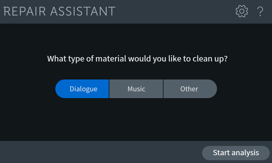
After selecting the source type, click the “Start analysis” button to begin analysis.
Analyzing Audio
During analysis Repair Assistant analyzes the selection for the following issues:
- Clipping
- Clicks
- Hum
- Noise
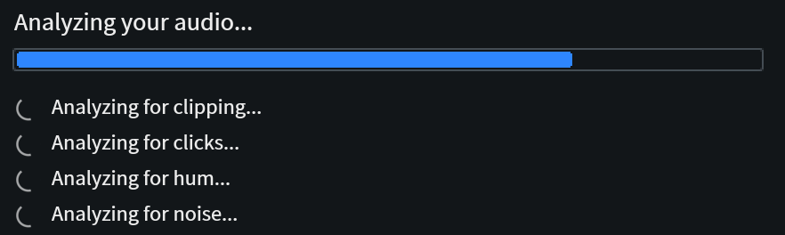
Repair Assistant Preferences
To bypass analysis of any of the above categories, click on the gear button in the upper right hand corner of the Repair Assistant window to open the Assistant Preferences.
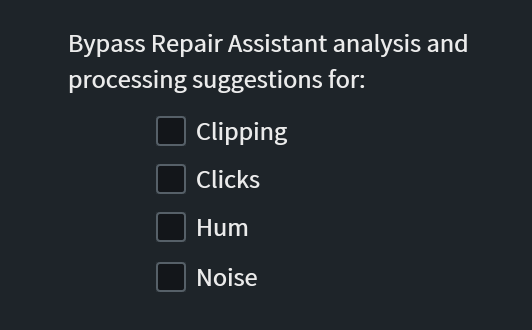
For more information about the RX Preferences menu, see the Preferences chapter.
No Problems Detected
If issues are not detected in any of the four categories, Repair Assistant will generate 3 basic clean-up processing chains for the selected source type using data learned during the analysis pass.
Generating Processing Chains
After analysis, Repair Assistant will generate three processing chains based on information gathered during analysis.
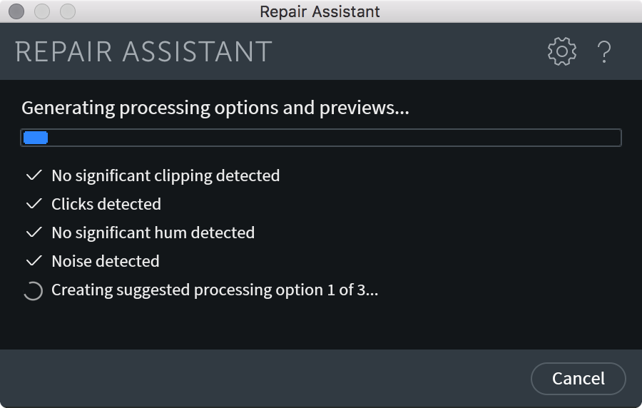
After the preview generation is complete, the Repair Assistant window will update and display playback buttons for the original audio and three processing chain preview buttons.
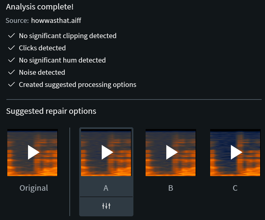
Each processing chain contains modules with settings based on information learned during analysis. e.g. Clipping thresholds (if applicable), noise profiles (if applicable), base hum frequency (if applicable), etc…
Preview Processing Chains
The processing chains can be previewed by clicking on the play buttons in the Repair Assistant window. Preview playback is limited to 10 seconds of the selection that was analyzed, or shorter if the selection was less than 10 seconds in length. Each processing chain preview will playback the same 10 seconds of audio.
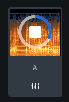
A 10 second preview of the unprocessed original audio is included to the left of the 3 preview buttons for easy before and after comparison.
The spectrogram displays drawn behind each preview play button reflects the processed spectrogram of the 10 second processing chain preview.
Processing Chain Tooltip
Hovering over a processing chain button will display a tooltip with a list of the modules included in the processing chain option.
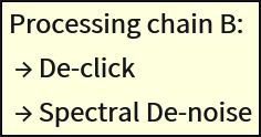
Intensity Variations
In RX Standard and Advanced, Repair Assistant can generate two additional intensity variations for each processing chain option. To generate intensity variations for a specific processing chain, click the button directly below the preview spectrogram display.
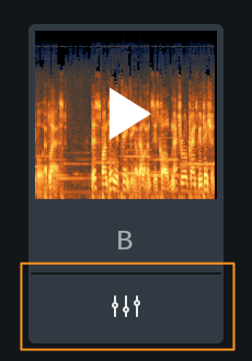
After clicking the intensity variant button, Repair Assistant will begin preparing the intensity variation preview. When the intensity variant preview have been generated, a slider will appear in place of the generate intensity variant button.
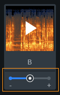
Adjusting the intensity variant slider will audition the same processing chain with modified settings.
RX Elements Intensity Variants
In RX Elements, Repair Assistant does not include intensity variant generation for each individual processing chain option. Instead, the three processing chains generated by Repair Assistant are intensity variations of the same processing chain.
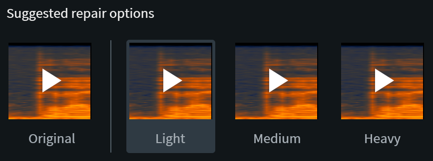
Render
To apply a Repair Assistant processing chain to the current selection, select the processing option in the Repair Assistant window and click the Render button in the bottom right hand corner of the window.

Open as Module Chain
The “Open as Module Chain” feature allows you to save a generated processing chain as a Module Chain preset, or make changes to the generated settings before rendering. To open a processing chain in the Module Chain, select the desired processing chain option and click the Open as Module Chain button in the Repair Assistant footer area.

Common RX Module Controls
The RX Audio Editor is designed to give you a range of processing options. Most of the modules in RX feature multiple processing modes, ranging from fast algorithms that sound great on most material to very time-intensive algorithms for critical applications.
Understanding the Presets, Preview and Compare controls will help you save time, especially when taking advantage of RX’s more powerful processing modes.
Presets

Each module in the RX Audio Editor features a preset menu that allows you to choose between factory presets and custom presets that you have saved. Any preset saved in a module in the RX Audio Editor can be opened in the corresponding RX plug-in, when applicable.
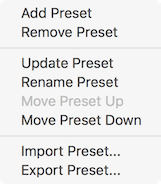
- Add Preset: Creates a new preset
- Remove Preset: Removes a preset from the drop-down list
- Rename Preset: Changes the name of a preset
- Set Preset Shortcut: Allows you to define a keyboard shortcut for any preset in order to recall and apply different module settings quickly
- Import Preset: Allows you to import presets (from another machine or another user, for example)
- Reload Preset: Rescans your preset directory for this module in order to refresh the available preset list
- Explore Preset/Reveal Presets in Finder: Opens Windows Explorer or Finder window to the location of your presets on disk
Preset directory locations:
- On Windows: C:\Documents and Settings\username\My Documents\iZotope\RX 7\Presets
- On Mac: username/Documents/iZotope/RX 7 Audio Editor/Presets/
Module Footer Controls

Preview
Many RX modules feature a Preview button in the bottom panel of the module window. Some modules don’t support Preview because of the time-intensive nature of their processing, in many of these cases the Compare settings option is available (explained below).
Preview allows you to make adjustments to controls and hear the results without the need to process and undo processing multiple times to achieve your desired results.
Preview will apply to your active selection or if no selection is made, Preview playback will start from the current playhead position. When Loop is enabled in the Transport, Preview playback will loop.
- Preview [Shift-Space]: Plays a pre-rendered preview of the module’s current settings on the selected audio. During preview, module settings can be adjusted and adjustments will be heard within the length of the current preview buffer. For most modules, the Preview buffer size is about a half of a second long, but the Preview Buffer Length can be adjusted by accessing the Preview Options, explained below.

- Bypass [Shift-B] Bypasses module processing during preview.
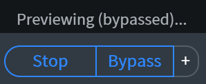
- Preview Options [+]: Allows adjustment of the Preview Buffer size.

For more CPU-intensive settings, like the highest quality algorithms in Spectral De-noise and the highest quality De-click settings, RX can buffer playback to allow you to preview these slower than real-time processes.
Note about Preview buffering
When Previewing module processing, the active buffer length for preview rendering is tinted red in spectrogram/waveform display.
Reduced Quality Preview
Some modules utilize a reduced quality preview mode. Learn more about this preview mode in the Reduced Quality Preview here.
Pre- and Post-Roll
When previewing an effect, it is often very helpful to hear a small portion of the unprocessed audio before hearing your processed selection. This can provide a much clearer comparison and allow you to more easily discern whether or not the current processing settings are producing the desired effect.
By default, RX will play back one second of unprocessed audio before and after the current selection when previewing your processing. The Pre- and Post-roll times can be defined in the Preferences > Misc window. RX can play up to ten seconds of audio before or after the previewed selection. Pre- and Post-Roll will also occur when previewing a looped region of audio
How to disable Pre- or Post-roll
Set the Pre- and Post-roll times in the Preferences > Misc tab to 0
Tip
Pre- and Post-roll can also be simulated manually by holding Control (Windows) or Command (Mac) to set the playhead to any desired position while preserving your audio selection. Once the playhead is set, clicking on Preview in the desired module will then start the Preview playback from the playhead position.
Compare
When you want to quickly try a lot of different settings, use the Compare feature. In some cases, you might not know what settings of a module will give you the best, most transparent results. By hitting the Compare button instead of the Process button, you can audition multiple settings of the same module and then audition the results side by side in the Compare Settings.
While one group of settings is processing in the background, you can return to the module and try a different group of settings. Learning to use the Compare Settings tool can save you from having to apply and undo a process multiple times just to find the right settings, making it a valuable time-saving feature.
Another advantage to using the Compare Settings tool is seeing the effect your settings have in the spectrogram/waveform display and spectrum analyzer.
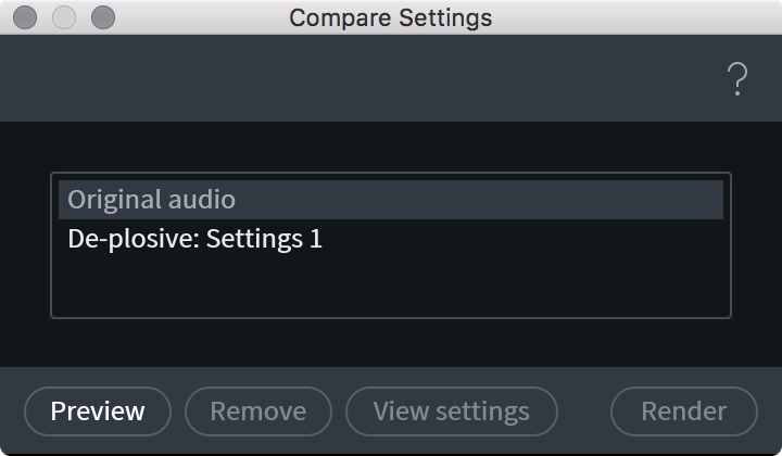
- Process Comparison List: Each time settings are sent to the Compare window, a new list item is created, by default titled “Settings 1,” “Settings 2,” etc.
- Preview: To hear (and see) the result of an item in the list, select that item and hit Preview.
- View Settings: Updates the controls to reflect the settings selected in the Process Comparison List
- Remove: Remove an item from the list.
- Rename: Allows you to rename items with more descriptive names.
- Render: Apply the selected list item to the audio file.
Reduced Quality Preview
Overview
Some RX modules require considerable latency to process audio. Normally, this high amount of latency would limit the ability to effectively preview module settings prior to rendering. A reduced quality preview mode has been implemented in a few modules, in order to allow for preview functionality in the RX Audio Editor application.
Reduced quality preview mode allows for preview playback in the following modules in the RX Audio Editor:
It is important to note that the reduction in quality only applies to preview playback and not to the rendered output of the modules listed above.
Module List
Overview
The Module List in the RX Audio Editor groups modules into the following categories: Repair, Utility, and Measurement. The modules displayed in the module list can be customized by saving a module list filter. The module categories can also be collapsed by clicking on the category header.
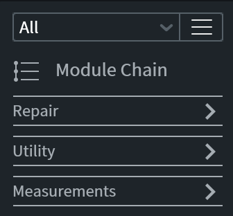
| Repair | Utility | Measurements |
|---|---|---|
| Ambience Match [ADV] | Azimuth [ADV] | Find Similar |
| Breath Control [STD & ADV] | Dither [STD & ADV] | Markers |
| Center Extract [ADV] | EQ [STD & ADV] | Spectrum |
| De-bleed [STD & ADV] | EQ Match [ADV] | Waveform Stats |
| De-click | Fade | |
| De-clip | Gain | |
| De-crackle [STD & ADV] | Leveler [ADV] | |
| De-ess [STD & ADV] | Loudness [ADV] | |
| De-hum | Mixing | |
| De-plosive [STD & ADV] | Normalize | |
| De-reverb [STD & ADV] | Phase | |
| De-rustle [ADV] | Plug-in | |
| De-wind [ADV] | Resample [STD & ADV] | |
| Deconstruct [ADV] | Signal Generator | |
| Dialogue Contour [ADV] | Time & Pitch [STD & ADV] | |
| Dialogue De-reverb [ADV] | Variable Pitch [STD & ADV] | |
| Dialogue Isolate [ADV] | Variable Time [STD & ADV] | |
| Interpolate [STD & ADV] | ||
| Mouth De-click [STD & ADV] | ||
| Music Rebalance [STD & ADV] | ||
| Spectral De-noise [STD & ADV] | ||
| Spectral Repair [STD & ADV] | ||
| Voice De-noise |
Workflow
How To Save a Module List Filter
- From the menu on the right of the List Filter Selector, select “Add List Filter”
- Choose a name for your new List Filter, hit return/enter to save the name
- Use the checkboxes to select the features you want to include
- Click the “Done Editing” button to save your new filter
Module Chain
Overview
The Module Chain allows you to apply the processing of multiple modules in series with the click of a button. You can choose from a variety of factory presets to get started or configure your own custom chain and save a preset to use again in the future.
Controls
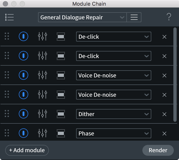
| Name | Description | |
|---|---|---|

|
Preset Menu | Save or load a module chain preset. More information about saving presets is covered in the Common RX Module Controls chapter. |

|
Module Chain Slot | Every module slot has a common set of options, explained in the following rows. |

|
Module Selector | Allows you to select the module to use in the given insert slot of the module chain. |

|
Module Order Handle | Click, hold and drag on this icon to change the order of the module in the module chain’s signal flow. |

|
Module Power Button | Enables/disables module processing. |

|
View Module | Opens the module window with settings loaded for the associated step in the module chain. |

|
Frequency Selection Settings | View frequency selection options for the current step in the processing chain. Allows for a specific frequency band to be processed within the current selection. |

|
Remove Module From Chain | Remove the associated module from the module chain. |

|
Add Module To Chain | Add module to the end of the processing chain. |
Ambience Match [ADV]
| Module & Plug-in (Audiosuite Only) |
|---|
Overview
The Ambience Match module lets you match the noise floor of one recording to another recording. For example, you can recreate the ambience of a live set on your ADR tracks.
The module analyzes the noise floor in your recording and creates a snapshot of it, similar to the noise print in the Spectral De-noise module. Then you can use this noise print to synthesize similar noise in another recording.
The Ambience Match algorithm analyzes an audio selection, rejects silence, and then finds the lowest common denominator (the noise that is common across the audio file) and treats that as the ambient profile.
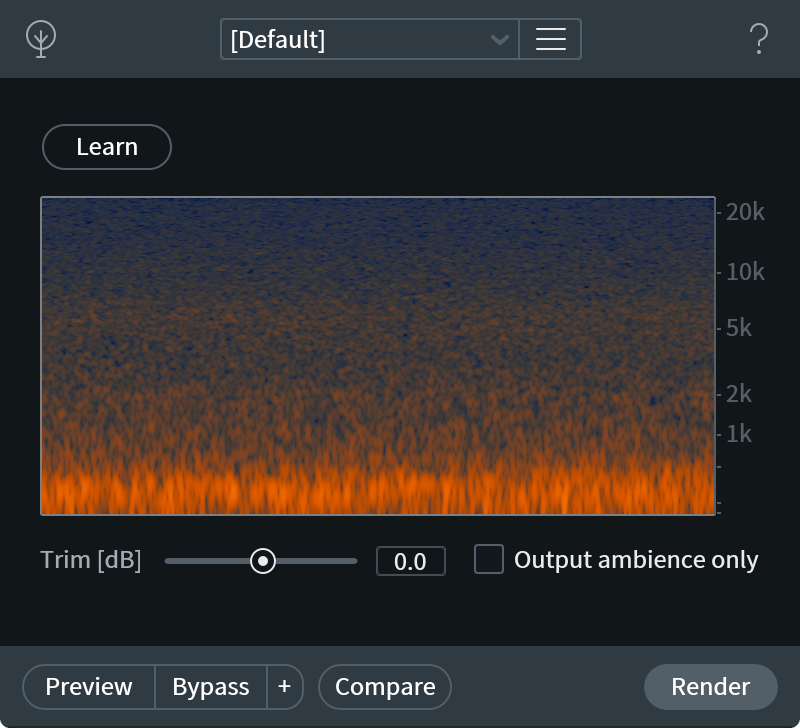
Workflow
Using Ambience Match module in the RX Audio Editor
To train Ambience Match, provide it with a selection of raw noise. If there is no single fragment of raw noise, or you want to save time, selections with speech can be used. The algorithm will intelligently discard speech and only leave noisy parts in the noise print.
To match the ambience between selections:
- Open the Ambience Match module in the module list
- Make a selection in a file.
- Click Learn.
- Make another selection.
- Adjust the Trim level as desired. The Trim control adjusts the level of synthesized ambience.
- Select Output Ambience Only if you want the selection replaced with only the ambience from the first selection.
- Click Render.
Note
The Ambience Match module cannot reduce the amount of ambience that already exists in the selection, it can only increase it. To reduce the ambience, use the Spectral De-noise module.
To create an Ambience Match preset:
- In Ambience Match, click the gear icon to the right of the preset drop-down menu.
- Select Add Preset.
- Enter the name for the new preset.
- Press Enter.
Using Ambience Match as an AudioSuite Plug-In
In addition to applying Ambience Match inside of the RX Audio Editor, it can also be used as an AudioSuite plug-in inside of Avid’s Pro Tools or Media Composer.
When using Ambience Match inside of Pro Tools or Media Composer, we recommend not learning from audio that contains fades within the selection or the handles. As Ambience Match establishes an ambient profile using the lowest common denominator, learning from audio that’s being faded in may result in inconsistent detection of the noise floor. Handles can be preserved by using Ambience Match in clip-by-clip mode.
Note about learning ambience on fades
When using Pro Tools, you may see an inconsistent result as a result of Pro Tools adding dithering to fades, which varies based on the session’s bit depth. Since this dithering noise almost certainly doesn’t match the material’s noise profile, this will throw off Ambience Match. If you’re running a session in 16 bits, the dither added by a fade will be sufficient enough to affect the detection algorithm. The problem is less pronounced in 24 or 32 bits. To adjust the bit depth of your session, go to Setup > Session in Pro Tools.
Breath Control [STD & ADV]
| Module & Plug-in |
|---|
Overview
The Breath Control module intelligently detects breaths in dialogue or vocal recordings and suppresses them. Removing and reducing breaths in recordings can be a time-consuming process for dialogue editors and music producers alike. Breath Control can help reduce the time spent on repetitive editing without sacrificing the quality of your dialogue or vocal recordings.
The Breath Control module analyzes your file and distinguishes breaths from dialogue or sung vocals based on their harmonic structure. If any piece of the incoming audio matches a harmonic profile similar to a breath, the module will suppress that portion of the audio until sung vocals are detected. Different from a ‘Threshold’ based process in which the module is only engaged once the audio has risen to a certain volume, Breath Control will perform its analysis regardless of level. This allows for accurate breath recognition for a multitude of quiet or loud vocal styles with minimal adjustment of the module’s controls.
Controls

- GAIN MODE: When Gain Mode is selected, the Breath Control module will reduce the gain of detected breaths by an absolute amount, regardless of the level of the breath. In some cases, this is desirable when trying to handle heavy breathing or as a way of removing all breaths from a particular spoken or sung vocal take. Depending on your settings, this can result in unnatural sounding results as the very quiet breaths may be inaudible, while the loud breaths will be reduced to a normal level.
- GAIN (dB): Sets the desired amount of gain reduction applied to all detected breaths, regardless of level.
- GAIN (dB): Sets the desired amount of gain reduction applied to all detected breaths, regardless of level.
- TARGET MODE: When in Target mode, the reduction amount of the ‘Target’ slider will set the level of detected breaths. This can result in more natural sounding breath reduction as detected breaths are only reduced when necessary. Loud and abrasive breaths will be reduced heavily, while quiet, natural sounding breaths will be left at the same volume.
- TARGET LEVEL [dBFS]: Sets the resulting desired level of all detected breaths above the set target.
- TARGET LEVEL [dBFS]: Sets the resulting desired level of all detected breaths above the set target.
- SENSITIVITY: This controls how sensitive the breath control plug-in is when detecting the harmonic structure of breaths in your audio.
- OUTPUT BREATHS ONLY: When enabled, only the audio of the detected breaths will be passed to the output of the module. This can help when setting the Sensitivity control in order to make sure that only the breathing in your audio is being processed.
Center Extract [ADV]
Overview
The Center Extract module preserves (using Keep Center) or removes (using Keep Sides) the center channel of a stereo file. Extracting the center will retain the center of a stereo field and attenuate everything on the sides, such as signals panned to the left or right. See the Examples & Use Cases section below for more contextual examples and additional information about Center Extract processing.
Controls
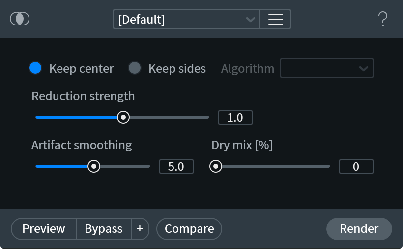
- KEEP CENTER: When the signal you want to preserve is even in both channels and noise is uneven between channels, extracting the center can remove a lot of noise.
- KEEP SIDES: If you want to preserve the wide stereo information and remove the center information, you can keep the sides of the signal instead.
- ALGORITHM: Two different algorithms are available:
- TRUE PHASE: Cancels the center with phase information and retains the original panning of the sides.
- PSEUDO PAN: Extracts the side information and artificially stereo-izes it into two channels.
- TRUE PHASE: Cancels the center with phase information and retains the original panning of the sides.
- ALGORITHM: Two different algorithms are available:
- REDUCTION STRENGTH: Controls the level of the preserved signal. Lower values will retain more information, higher values will discard more information.
- ARTIFACT SMOOTHING: Helps to reduce or eliminate the “musical noise” that is often characteristic of FFT-based processing. Musical noise can be described as how something may sound underwater. Increase this slider if your output sounds watery, but decrease it when too much smoothing makes your audio sound dull.
What is an FFT?
- Fast Fourier Transform: a procedure for the calculation of a signal frequency spectrum. The greater the FFT size, the greater the frequency resolution, i.e., notes and tonal events will be clearer at larger sizes. However, when using FFT-based processing, the more audio you remove from your source, the more likely you are to create undesirable artifacts.
- Fast Fourier Transform: a procedure for the calculation of a signal frequency spectrum. The greater the FFT size, the greater the frequency resolution, i.e., notes and tonal events will be clearer at larger sizes. However, when using FFT-based processing, the more audio you remove from your source, the more likely you are to create undesirable artifacts.
- DRY MIX [%]: Controls the amount of unprocessed signal mixed into the processed signal. Useful for reducing artifacts introduced by processing by preserving the original characterisitics of your audio.
More Information
Tip: Use Azimuth before Center Extract for best results
It is often a good idea to make sure stereo channels are balanced by running Azimuth correction before using Center Extract.
Notes on Center Extract Availability
- Center Extract is not available when Composite View is active.
- Center Extract processing is not available on mono files. The nature of Center Extract processing makes it unapplicable to mono files because they lack stereo field information.
Use Cases
| Using Center Extract as an alternative to Mid-Side Encoding |
|---|
| Center channel extraction will preserve a stereo image if the side channels are retained. This can make it more desirable in some cases than Mid-Side encoding (which would sum left and right hard pans into one channel). |
| Use Keep Center to Reduce noise in stereo files transferred from a mono source |
|---|
| A mono record transferred to a stereo tape would have side channel noise that would be suppressed by extracting the center channel using Keep Center. |
| Use Keep Sides to Remove vocals from a stereo recording |
|---|
| The lead vocal track, in many popular mixes, is typically panned to the center of the mix. Panning something to the center results in equal information being present in the side (Left and Right) channels. |
| Using the “Keep Sides” processing mode will retain the unique side channel information present in a file, and reduce the Center channel. |
| This is useful for karaoke-style removal of vocals from a song, especially because the process results in a coherent stereo image. |
De-bleed [STD & ADV]
Overview
De-bleed reduces the leakage of one signal into another, such as when vocals bleed into a guitar microphone, or when a click track fed into headphones bleeds into an open mic.
The De-bleed module learns a bleed relationship between two tracks. In the descriptions below, these two tracks are referred to as:
- BLEED SOURCE TRACK: This track contains only the bleed source audio.
- ACTIVE TRACK: This track contains the audio present in your source track (bleed), mixed in with the audio you want to preserve.
De-bleed relies on a relationship existing between your Active track and Bleed Source track in order to function properly and provide the best results. In order to properly establish the relationship between the Active and Bleed Source tracks, the following requirements must be met:
| De-bleed requires 2 tracks to process |
|---|
| De-bleed requires 2 tracks (Bleed Source Track & Active Track) to be open in the RX Audio Editor. |
| Bleed Source and Active Track must have matching sample rates |
|---|
| The sample rates of the Bleed Source Track and Active Track must match in order to process using De-bleed. |
| Using tracks of different sample rates may indicate that the tracks are not related. |
Tip: How to correct sample rate differences
If you need to correct the sample rates of your bleed source and active track selections in the De-bleed module, you can use the Resample module in the RX Audio Editor to correct sample rate differences between your files, if necessary.
| Time alignment of the Bleed Source and Active tracks is important |
|---|
| The Bleed Source Track and Active Track must be time aligned within a few milliseconds of each other. |
| “Time aligned” means that if the two files were played back together, they would sound in sync. So if the same audio events are occurring at the same points in the timeline for both the Bleed Source and Active tracks, this means they’re time aligned. |
Tip: How to correct time alignment issues
You can adjust the length or timing of files in the RX Audio Editor by:
- Using the “Cut” edit operation, Command+X (Mac) or Ctrl+X (Windows), to remove the active selection.
- Insert Silence using the Signal Generator module to adjust the length of your file.
Workflow
- Import the bleed source file (“Bleed Source Track”) and the file you are removing bleed from (“Active Track”) into the RX Audio Editor. Ensure that the files are in sync (instructions above).
- Open the De-bleed module.
- Ensure that the “Active Track” name that is displayed in the De-bleed module is the file you wish to modify.
- In the De-bleed module, select the Source Track from the “Bleed Source Track” drop-down menu.
- In the active file tab (Active Track), make a selection where the bleed is most obvious.
- Click the Learn button in the De-bleed module. (Learn analyzes the general relationship between the Bleed Source and the Active Track.)
- After the Learn pass is complete, select part or all of the Active Track and click Process.
Controls
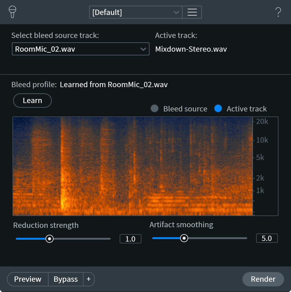
- BLEED SOURCE TRACK SELECTION MENU: Select the Bleed Source track from this dropdown.
- ACTIVE TRACK: Displays the name of the track tab you are currently viewing.
- LEARN: Learns the relationship between the two tracks.
- BLEED PROFILE DISPLAY: After learning the bleed profile, this displays a portion of the relationship captured between the two tracks. Toggle between the Bleed Source and Active track displays to check that the bleed present in the bleed source track is present and aligned with the bleed in your active track.
Bleed source display:
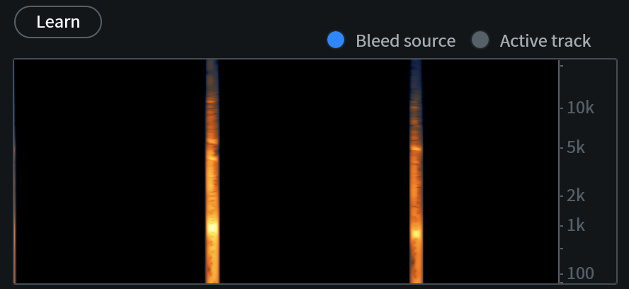
Active track display:
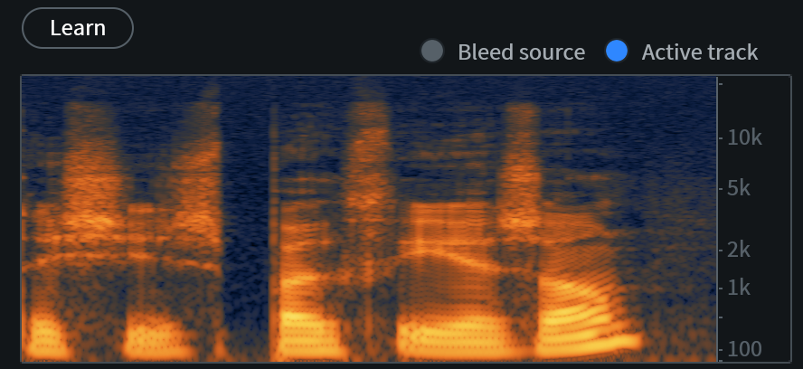
- STRENGTH: Determines the amount of bleed reduction applied during processing. Higher Strength values may result in the removal of audio you wish to preserve. It is recommended you start with lower strength values and increase the values if needed to achieve the most desirable results.
- ARTIFACT SMOOTHING: Helps to reduce or eliminate the “musical noise” that is often characteristic of FFT-based processing. Musical noise can be described as how something may sound underwater. Increase this slider if your output sounds watery, but decrease it when too much smoothing makes your audio sound dull.
What is an FFT?
- Fast Fourier Transform: a procedure for the calculation of a signal frequency spectrum. The greater the FFT size, the greater the frequency resolution, i.e., notes and tonal events will be clearer at larger sizes. However, when using FFT-based processing, the more audio you remove from your source, the more likely you are to create undesirable artifacts.
De-click
| Module & Plug-in |
|---|
Overview
The De-click module’s sophisticated algorithm analyzes audio for amplitude irregularities and smoothes them out. This means that you can use De-click to remove a variety of short impulse noises, such as clicks caused by digital errors, mouth noises, and interference from cell phones.
Controls
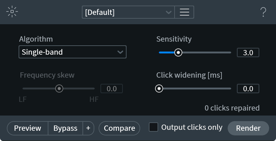
- ALGORITHM: Provides options for adjusting the configuration and processing quality of click interpolation, depending on the types of clicks and pops present in the audio.
- SINGLE BAND: Processes quickly and works well on very narrow “digital” clicks
- MULTI-BAND (PERIODIC CLICKS): Uses multi-band processing for removing regularly repeating clicks with a wider spectrum, or regular clicks that have concentrated low or high energy (like thumps or optical soundtrack perforation noise)
- MULTI-BAND (RANDOM CLICKS): Uses multi-band processing for wider vinyl clicks and thumps, with a protective algorithm for preserving periodic audio elements characteristic to certain instruments such as brass or vocals
- LOW LATENCY: Works well on mouth clicks and other clicks that cannot be handled by other algorithms. This mode has very low latency and is suitable for real-time work in RX De-click plug-in.
- SINGLE BAND: Processes quickly and works well on very narrow “digital” clicks
- SENSITIVITY: Determines how many clicks are detected in the signal. Increasing sensitivity can impact plosives, which can in turn reduce or damage the original signal.
- FREQUENCY SKEW: Adjusts the weighting of click removal toward higher or lower frequency clicks. Negative values are more suitable for generic clicks such as those found on vinyl recordings. A setting of zero or above targets mouth clicks in the middle frequencies.
Note
- Frequency skew is not available when using the Single Band Algorithm option.
- Frequency skew is not available when using the Single Band Algorithm option.
- CLICK WIDENING: Extends the repair area around detected clicks, compensating for mouth sounds such as lip smacks that have a decay.
- OUTPUT CLICKS ONLY: Outputs the difference between the original and the processed signals (suppressed clicks).
Instant Process Tool
[STD & ADV]
The Instant Process Tool offers a smart De-click mode, which instantly applies the active settings from the De-click or Interpolate modules. Simply put, you may make any selection, and this mode will automatically remove all clicks present in that selection. This is particularly useful for editing a dialogue file, mismatching sample rate clicks and pops, and vinyl clicks.
If you’ve made a selection under 4000 samples in length, Instant Process will automatically use the Interpolate algorithm. Interpolate will fill the selection with audio information based on the surrounding audio.
For selections above 4000 samples, Instant Process will use the current settings of the De-click module. De-click is effective on selections above 4000 samples in size, identifying clicks in relation to desirable audio, and intelligently separating and removing the clicks.
For example, if the De-click module is indicating that a preset named ‘Remove mouth clicks’ is loaded, these settings will be applied every time you use the Instant Process Tool in ‘De-click’ mode (on selections longer than 4000 samples).
De-clip
| Module & Plug-in |
|---|
Overview
De-clip repairs digital and analog clipping artifacts that result when A/D converters are pushed too hard or magnetic tape is over-saturated. It can be extremely useful for rescuing recordings that were made in a single pass, such as live concerts or interviews, momentary clipping in “perfect takes”, and any other audio that cannot be re-recorded.
De-clip will process any audio above a given threshold, interpolating the waveform to be more round. Generally, the process is as easy as finding the clipping you want to repair, then setting the threshold just under the level where the signal clips.
Controls

- HISTOGRAM METER: Displays waveform levels for the current selection as a histogram. The histogram meter helps you set the Threshold control by displaying the audio level where the waveform’s peaks are concentrated. This usually indicates at what level clipping is present in the file. The longer the line for the histogram is, the more energy is present at that amplitude.
- HISTOGRAM ZOOM CONTROLS: The histogram’s range can be scaled if you need a better view of your signal. Use the (+) and (-) buttons to scale your display and value resolution for the De-clip module. These buttons reduce (+) and/or expand (-) the range of the threshold slider and histogram. You may want to extend the histogram range when the clipping point is lower than what you can see on a histogram or if you don’t see anything on the histogram.
Note on histogram updating in the application vs. the De-clip plug-in
- In the RX Audio Editor, the Histogram meter updates based on selection: Select a section of the recording where clipping is prominent and De-clip will analyze the levels of the program material. If clipping is present in the selection, it will usually appear as a horizontal line in the histogram that extends all the way across the meter.
- In the De-clip Plug-in, the histogram runs as a real-time meter.
What is a histogram?
- A histogram is an analytical tool that displays how many samples are present at a given signal level over a window in time. The longer the line for the histogram is, the more energy is present at that amplitude.
- If a lot of energy tends to collect near the top and bottom edges of a waveform, that waveform is probably clipped and distorted.
- THRESHOLD [dB]: Defines the level used for detection of clipped intervals. Generally, this should be set just below the actual level of clipping. To set the threshold, move the Threshold slider until it lines up with the place in the histogram just below where clipping is concentrated.
Understanding the Clipping Threshold overlays
- Adjusting the Clipping Threshold will display a blue line within the histogram and a gray line on the waveform itself (when the De-clip Threshold effect overlay). These lines indicate the audio information that will be considered as “clipping” by the de-clip algorithm.
Using the De-clip Threshold Effect overlay in the Spectrogram/waveform view
- By default, De-clip Threshold is enabled in the View > Effect Overlay menu.
- When enabled and the De-clip module is open, the De-clip threshold overly will be displayed in the spectrogram/waveform display.
- You can adjust the Threshold controls in the De-clip module by adjusting the Threshold overlay lines in the spectrogram display.
- You can use the mousewheel on the waveform amplitude ruler to adjust the threshold control values.
- THRESHOLD LINK: Toggles the ability to adjust positive and negative clipping thresholds independently.

- When this option is enabled, you can adjust the positive and negative clipping Threshold controls independently. This is useful in cases where more clipping is occurring on one side of your waveform.
- You can also set asymmetric de-clipping thresholds directly from the waveform by toggling the lock box between the threshold controls on the waveform display.
- When this option is enabled, you can adjust the positive and negative clipping Threshold controls independently. This is useful in cases where more clipping is occurring on one side of your waveform.
- SUGGEST: Calculates suggested threshold values based on the levels in your current selection.
QUALITY: Controls the interpolation processing quality. There are three quality modes in the De-clip module: Low, Medium, and High.
De-clip Quality mode notes
- Low quality mode processes very quickly.
- High quality mode processes slowly but is capable of achieving better results.
- In many cases you will find that Low quality mode gives you great results. To save time, always start by previewing the Low quality modes first. You can also use the Compare feature to try multiple modes and preview the results.
- Low quality mode processes very quickly.
MAKEUP GAIN [dB]: Selects the gain to be applied to the selection after De-clip.
When to use the make-up gain control
- The De-clip process causes an increase in peak levels. The Makeup gain control can be used to prevent the signal from clipping after processing. It is also useful for matching the level after processing to unprocessed audio outside of the selection.
- The De-clip process causes an increase in peak levels. The Makeup gain control can be used to prevent the signal from clipping after processing. It is also useful for matching the level after processing to unprocessed audio outside of the selection.
POST-LIMITER: Applies a true peak limiter after processing to prevent the processed signal from exceeding 0 dBFS.
- De-clip usually increases signal levels by interpolating signal segments “above” the clipping point, which can make the signal clip again if the waveform format offers no headroom above 0 dBFS.
- If the post-limiter is disabled, the restored intervals above 0 dBFS can be safely stored even without makeup gain as long as the file is saved as 32-bit float. Intervals above 0 dBFS will clip when played back through a digital-analog converter.
- De-clip usually increases signal levels by interpolating signal segments “above” the clipping point, which can make the signal clip again if the waveform format offers no headroom above 0 dBFS.
More Information
Suggestions for severe distortion
- For certain situations, using the Deconstruct module to extract the noise components of the distortion can help remove additional artifacts beyond the clipped peaks in a waveform.
- In cases where severe distortion is visible on the spectrogram, the Spectral Repair tool can be used to select those problem areas, and attenuate or replace them with undistorted audio.
Visual Examples
Before & After Clip Repair
A waveform before and after clip repair. The after example (bottom) shows the original repaired waveform (faded) and the post-limiting waveform (bright).
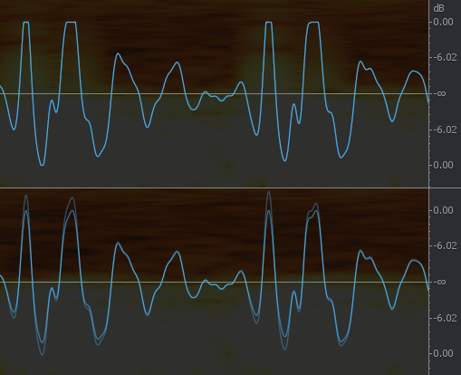
Unlinking Threshold Controls To Curb Asymmetric Clipping
This problematic waveform (grey) shears off around −13 dB on only the positive side of the waveform (the histogram on the right shows the extra positive energy of clipped audio). Extra processing of the negative side would be unnecessary, so the Threshold controls can be unlinked to process above −13 dBFS on the positive side only. The resulting waveform is drawn in blue above the grey sheared peak.
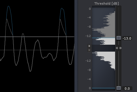
De-crackle [STD & ADV]
| Module & plug-in |
|---|
Overview
When an audio signal contains many clicks that are close together and low in volume, this is described as crackle. De-crackle is very effective at removing these audio problems and even more effective if it is run after De-click has eliminated the worst offending clicks.
Controls
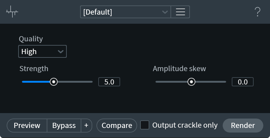
- QUALITY:
- LOW quality offers fast processing
- MEDIUM quality will remove periodic, rapidly repeating clicks
- HIGH quality will help preserve the tonal qualities of a signal
- LOW quality offers fast processing
- STRENGTH: Controls the amount of crackle that is detected and repaired.
- AMPLITUDE SKEW: Biases the processing toward higher or lower volume crackle. If the crackle accompanies transients and other high-level signal passages (such as during clipping), set this control more to the right. If the crackle mostly happens during low-amplitude signal passages, set this control more to the left.
- OUTPUT CRACKLE ONLY: Outputs the difference between the original and processed signals (suppressed crackle).
De-ess [STD & ADV]
| Module & Plug-in |
|---|
Overview
De-ess attenuates or reduces sibilance, the harsh high-frequency sounds that come from “S,” “F,” “X,” “SH,” and a soft “C.”
Controls
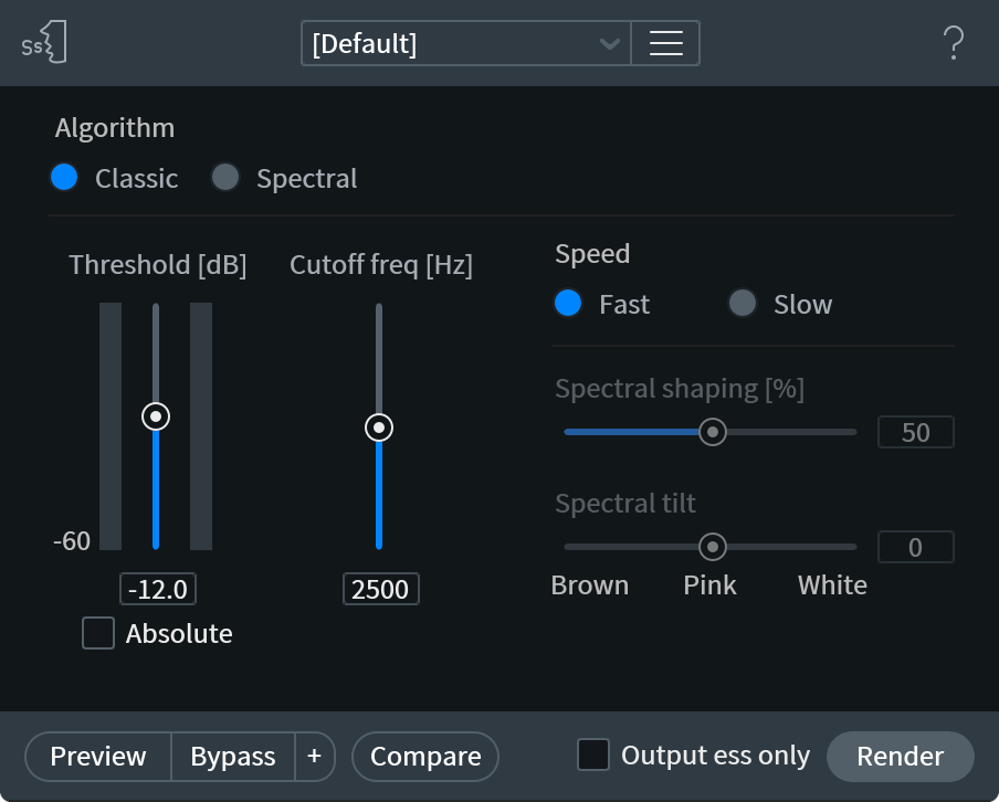
- MODES: The De-ess module offers two processing algorithms:
- CLASSIC MODE: Detects sibilants and attenuates them with a broadband gain envelope. Since attenuation is applied to all frequencies, this mode is less targeted than Spectral De-ess.
- SPECTRAL MODE: Offers a more transparent, intelligent, and frequency-specific type of de-essing than Classic Mode. Spectral Mode only attenuates the high frequencies where sibilance is most active, leaving the lower frequencies untouched.
- CLASSIC MODE: Detects sibilants and attenuates them with a broadband gain envelope. Since attenuation is applied to all frequencies, this mode is less targeted than Spectral De-ess.
How does the Spectral De-ess processing work?
Spectral De-ess is a multiband compressor with dozens of bands. It’s able to compress the level of sibilants, shape their spectra, and avoid modulation of ambient noise. Each band can operate independently or with a link to adjacent bands (adjusted by the Spectral Shaping slider, explained below) and band thresholds can be adjusted for the desired shape of a sibilant (achieved by adjusting the Spectral Tilt slider, explained below)
- THRESHOLD: Determines the level at which the De-ess module begins compressing sibilance. The Threshold control has two modes that determine how it reacts to incoming signal level. It is specified in decibels, relative to speech level (Relative Mode) or full scale (Absolute Mode).
- RELATIVE MODE: Determines the level of speech and sets the threshold relatively to that level. This is the default Threshold mode, Relative mode is active when the “Absolute” checkbox below the Threshold slider is not checked.
- ABSOLUTE MODE: Sets the threshold to a decibel level below full scale (dBFS). This mode is enabled by checking the “Absolute” checkbox below the threshold slider.
- RELATIVE MODE: Determines the level of speech and sets the threshold relatively to that level. This is the default Threshold mode, Relative mode is active when the “Absolute” checkbox below the Threshold slider is not checked.
- CUTOFF FREQUENCY: Specifies the crossover point between speech (to be preserved) and sibilance (to be reduced). The Cutoff frequency value functions as the lower boundary for sibilance detection.
SPECTRAL FLATTENING: Spectral Flattening determines how much the spectral shape of the sibilant is changed. A setting of 0% leaves the natural shape of the sibilance by applying uniform compression across all bands. A setting of 100% flattens the shape of the sibilant toward a specified noise profile (see Spectral Tilt).
Understanding Spectral Flattening
- Think of Spectral Flattening as a way to fine tune the strength of the sibilant processing. The flatter you go, the more the sibilant is reduced.
- Think of Spectral Flattening as a way to fine tune the strength of the sibilant processing. The flatter you go, the more the sibilant is reduced.
SPECTRAL TILT: Spectral Tilt creates a target noise profile for the sibilance. A setting of 0 creates a natural spectral decay similar to pink noise. Values below or above 0 create a profile that is heavier in low frequencies (like brown noise) or high frequencies (like white noise). Spectral Tilt is most effective when the Spectral Shaping control is set to a non-zero value.
Understanding Spectral Tilt
- Spectral Tilt gives you the flexibility to determine what the ideal shape of your high frequency signal could be. Moving the shape toward brown noise moves it toward a darker sound. Moving the shape toward white noise provides a brighter result. Together with flattening and threshold, you can determine how much shaping takes place.
- Spectral Tilt gives you the flexibility to determine what the ideal shape of your high frequency signal could be. Moving the shape toward brown noise moves it toward a darker sound. Moving the shape toward white noise provides a brighter result. Together with flattening and threshold, you can determine how much shaping takes place.
SPEED: Sets the attack and release times for the processing. Attack times are program-dependent in both modes.
- FAST: Uses quicker attack and release times.
- SLOW: Uses longer attack and release times.
Are you using the right speed setting?
- Is De-ess smoothing out the transients too much?
Settings that are too fast can reduce the high frequency signal too much in the initial transient phase and can introduce a smoothing effect that reduces useful high frequency definition. Try using Slow mode to mitigate this problem. - Is De-ess causing pumping in the high frequencies?
If the settings are too slow, the processor won’t recover quickly enough, resulting in too much high frequency attentuation. Try using Fast mode to mitigate this problem.
- Is De-ess smoothing out the transients too much?
- FAST: Uses quicker attack and release times.
De-hum
| Module & Plug-in |
|---|
Overview
De-hum is designed to remove persistent tonal noise, like the AC hum that can be caused by poor electrical grounding. De-hum includes a series of notch filters that can be set to remove both the base frequency of the hum, usually 50 Hz (Europe) or 60 Hz (USA) as well as any harmonics. The De-hum module is effective for removing hum that has up to seven harmonics above its primary frequency.
Controls
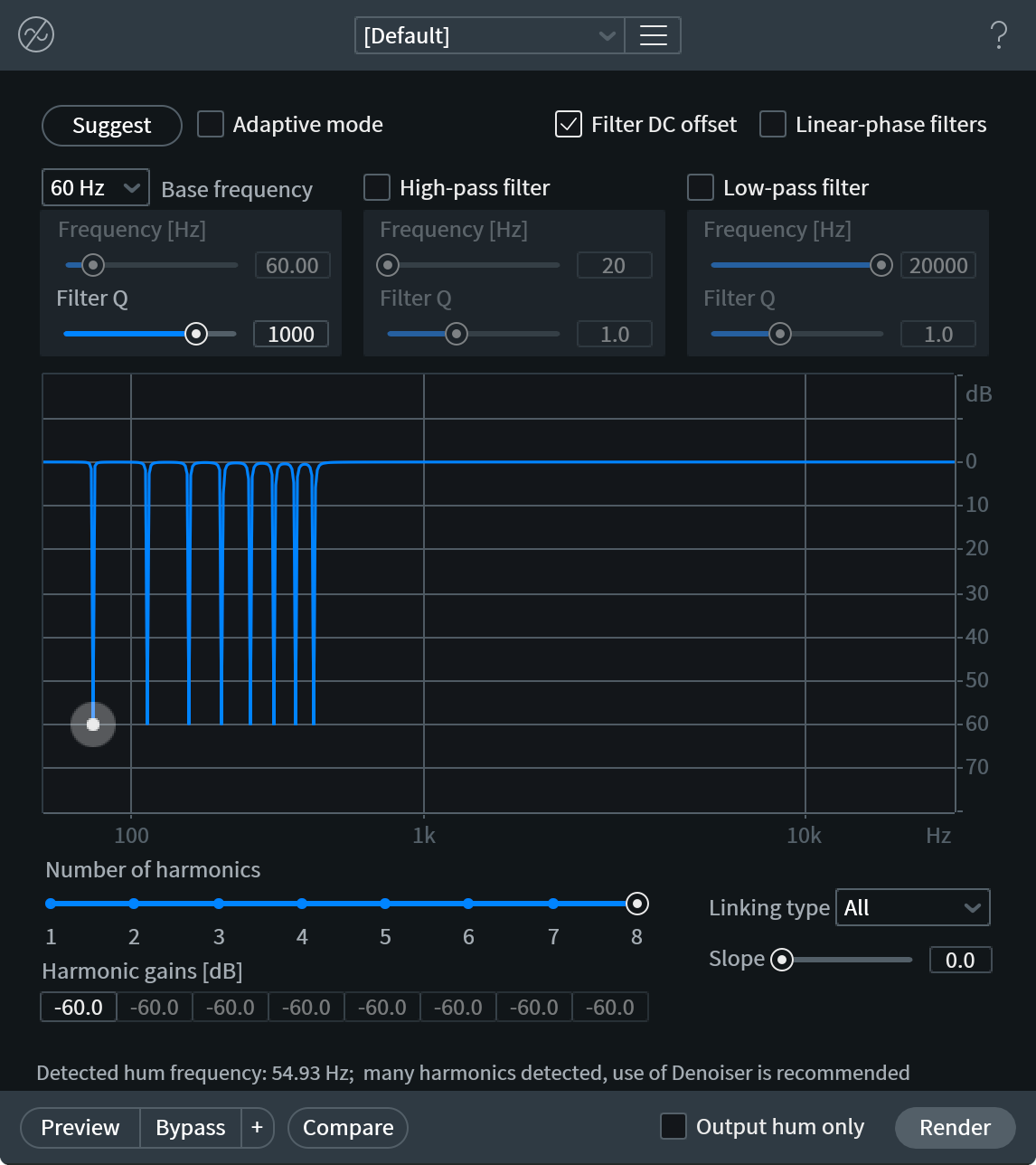
- BASE FREQUENCY: Sets the fundamental frequency of the hum to be removed. The Free option unlocks the Notch Frequency control and allows you to manually identify the fundamental. With Preview engaged, adjust the slider until you find the point where the hum is appropriately reduced.
Tip
You can also use the Spectrum Analyzer to help identify the base frequency of the hum.
- SUGGEST: De-hum can intelligently identify the noise profile of the hum in your audio. Make a selection containing the hum in isolation, and click the Suggest button. This will automatically set the Base Frequency based on the learned profile. If you cannot find a selection of hum in isolation, RX can analyze any audio with prominent hum, but the results may not be as useful.
- ADAPTIVE MODE: Allows De-hum to adjust the notch filters based on changes in the audio over time. In this mode, RX will analyze incoming audio to determine what is hum and what is desired audio material. Adaptive mode will work better with hum that changes in pitch throughout the file.
- FILTER Q: Controls the bandwidth of the notch filters for the base frequency and all of the harmonics.
LINEAR-PHASE FILTERS: Linear-phase enables FIR (Finite Impulse Response) filters with a high FFT size. These filters provide very accurate frequency response with no change in phase at the expense of latency and filter pre-ringing.
Disabling Linear Phase (FIR) filters
- When Linear Phase is disabled, De-hum will use minimum-phase IIR filters. These are also very accurate, and are only susceptible to post-ringing, which is usually less noticeable than the pre-ringing introduced by FIR filters.
- Latency Consideration: Disabling Linear Phase Filters will reduce the latency used by De-hum when it is being used as a real-time plug-in.
- When Linear Phase is disabled, De-hum will use minimum-phase IIR filters. These are also very accurate, and are only susceptible to post-ringing, which is usually less noticeable than the pre-ringing introduced by FIR filters.
HIGH/LOW-PASS FILTERS: These traditional filters come ahead of the De-hum notch filters, and allow for frequencies to pass above or below a certain cutoff point. These can be useful for tackling extreme hum or buzz.
- FREQUENCY [Hz]: sets the cutoff frequency for the filter
- Q: Sets the bandwidth of the filter (or dB/octave cut). In the default IIR filter mode with a high Q setting, you may notice a resonance at the cutoff frequency characteristic of traditional analog filters. That resonance can be mitigated by engaging the Linear-phase filters.
- FREQUENCY [Hz]: sets the cutoff frequency for the filter
NUMBER OF HARMONICS: Because harmonics often accompany the fundamental frequency of a hum, De-hum can also attenuate these overtones with notch filters. Using the Number of Harmonics control, you can select up to 7 harmonics above the fundamental. The spectrogram display can make it easy to identify the harmonics. After selecting the number of harmonics, use the Slope control to set how aggressively the higher harmonics are attenuated.
LINK HARMONICS: Connects the gain controls of the notch filters.
- ALL: presents a single node on the display for controlling the gain of all the notch filters. This is the default setting.
- ODD/EVEN: presents two nodes on the display, one for controlling the gain of the fundamental frequency and even harmonics, and another for controlling the 1st harmonic and any following odd harmonics.
- NONE: presents individual gain nodes for the fundamental and each harmonic.
- ALL: presents a single node on the display for controlling the gain of all the notch filters. This is the default setting.
SLOPE: When harmonics are linked, this controls the harmonic slope of the gain nodes for each overtone. As the harmonic order increases, the gain level resolves closer to 0 dB. When the Link Harmonics control is set to Odd/Even, a separate control appears that affords independent control over the slope for both odd and even harmonics.
HARMONIC GAINS [dB]: This section provides a numerical readout of the notch filter gain settings in decibels. You can also manually enter gain settings for the fundamental, or any of the harmonics if Link Harmonics is set to None.
FILTER DC OFFSET: This checkbox will engage a filter to remove any DC (direct current) offset that sometimes occurs in A/D converters or analog circuits used in the recording process.
OUTPUT HUM ONLY: Selecting this check box will isolate the hum that is being removed. This is useful for fine-tuning your settings. Identify a section of your file where the hum is mixed with other material, select this mode, and click Preview. Now adjust parameters like Filter Q and Slope control to maximize hum removal, thus minimizing the effect on the program material.
More Information
Alternative Modules to use for Complex Hum Issues
- Spectral De-noise For hum that has many harmonics that extend into higher frequencies (often described as “buzz”), try using Spectral De-noise. Spectral De-noise features tonal noise reduction controls that can make short work of harmonic hum and buzz across the entire spectrum.
- De-click Some very high frequency buzz can also be removed with the De-click module.
Visual Example
This image shows the spectrogram of a file with 3 harmonics of a 60 Hz Hum:
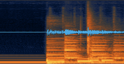
De-plosive [STD & ADV]
| Module & Plug-in |
|---|
Overview
A plosive is a consonant speech sound that occurs when the vocal tract briefly blocks the flow of air during speech. When the block in the vocal tract is resolved, an audible release of pressure occurs, called a plosive. Pop filters (in a studio) or wind filters (on location) are commonly used when recording vocals or dialogue, in order to reduce the popping effect that can occur when the higher pressure plosive signal comes into contact with the diaphragm of a microphone.
De-plosive can intelligently identify, separate and reduce plosives in an input signal while still preserving the fundamental frequency content and harmonics of the dialogue.
Controls
The following section describes the controls available for refining plosive reduction.
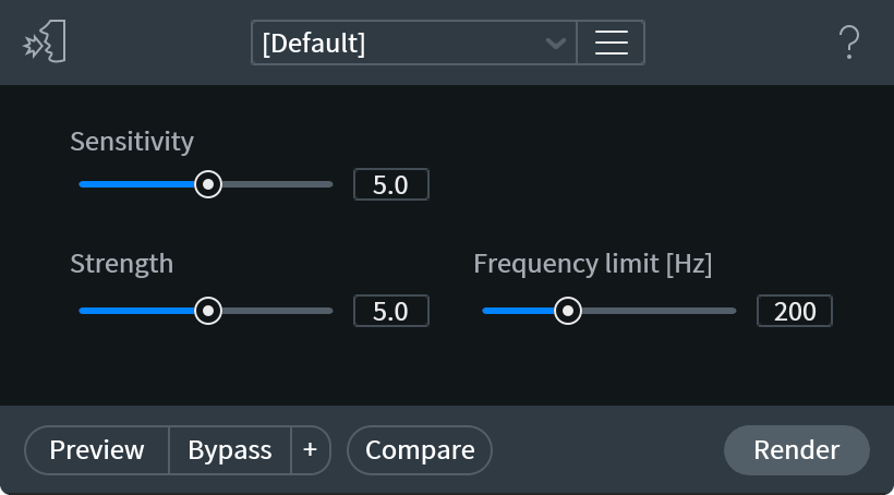
Sensitivity
Adjusts how much of the input audio will be categorized as a plosive. Sensitivity has a greater effect on the overall effectiveness of plosive reduction than simply increasing the Strength control.
- Lower values will instruct the algorithm to narrowly define what it will detect as a plosive. This may result in less overall reduction of plosives with the benefit of maintaining the quality of the speech signal.
- Higher values will instruct the algorithm to more broadly detect plosives in the input signal, which may result in too much of the speech signal being identified as, and subsequently reduced with, the plosive signal content.
Strength
Adjusts the amount of reduction applied to the detected plosive signal content. Higher values can result in significant plosive reduction at the cost of decreasing the quality and clarity of the speech signal. To maintain the speech signal while still reducing plosives, try increasing the Sensitivity control and decreasing the Strength control.
Frequency Limit [Hz]
Sets the upper frequency boundary for plosive reduction. Plosives typically manifest between 20Hz to 300Hz, but may sometimes reach as high as 500Hz. Setting this control just above where the plosives are occurring in the input signal can help reduce unwanted reduction of frequency above where the plosives are occurring.
Identifying plosives in the spectrogram display
The spectrogram can be used to help determine the highest plosive frequency in the input signal. Plosives are caused by small bursts of air pressure hitting the diaphragm of a microphone which results in an increase in amplitude. The colors used to represent signals in the spectrogram are tied to the amplitude of a signal. Darker colors represent lower amplitudes and brighter, more vibrant colors represent higher amplitudes. Plosives will generally appear brighter than the signal content that surrounds them.
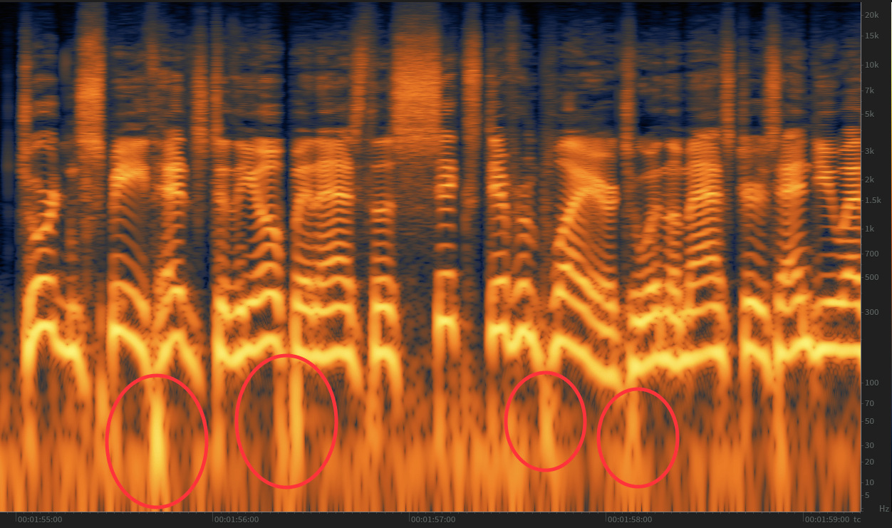
Recommendation: Use De-plosive before applying a high pass filter
De-plosive attempts to detect plosives between 20 to 80 Hz. If the input file has already been filtered with a high-pass filter, it is possible that plosive detection will not function correctly. To achieve the best results, it is recommended that De-plosive be used before applying a high-pass filter.
De-reverb [STD & ADV]
| Module & Plug-in |
|---|
Overview
De-reverb gives you control over the amount of ambient space captured in a recording. It can make large cathedrals sound like small halls and make roomy vocals sound like they were recorded in a treated space.
De-reverb processes audio according to the reverberant/direct ratio (also known as wet/dry ratio) detected in the signal. It can learn your audio to suggest some frequency and decay time settings, or you can estimate these yourself.
Controls
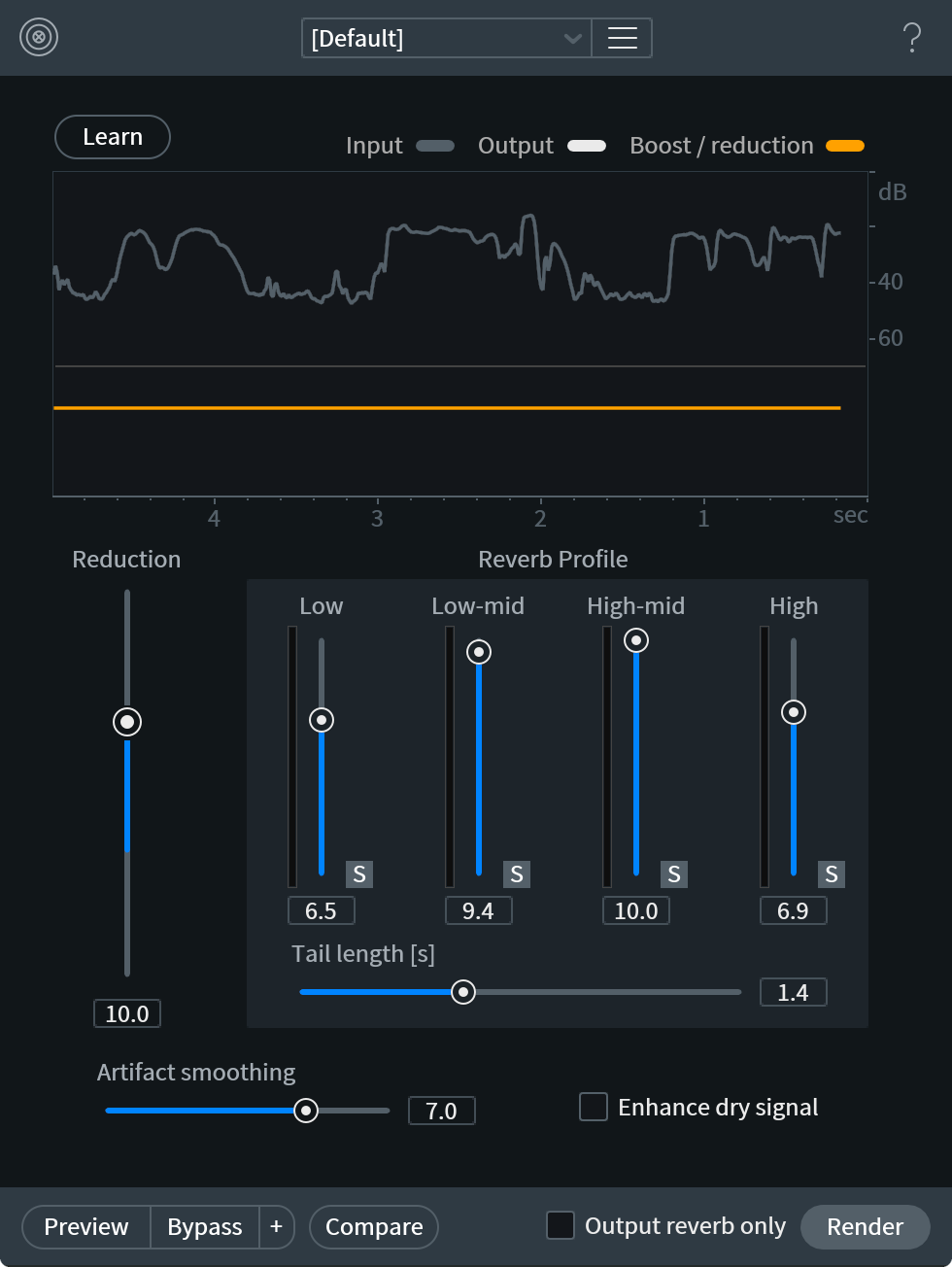
- LEARN: Teaches De-reverb how much reverb is in your signal.
- The Learn feature analyzes the signal and determines the wet/dry ratio per frequency of your signal, as well as the overall rate of decay of reverb.
- When the Learn operation completes, the Reverb Profile and Tail Length controls will be set to their suggested values.
- The Learn operation can be performed on any reverberant audio.
Recommendation
- We strongly recommend using the Learn feature on a selection of audio that starts with some noise floor (or room tone), is several seconds long, and includes both the direct signal and its reverberant tails.
- We strongly recommend using the Learn feature on a selection of audio that starts with some noise floor (or room tone), is several seconds long, and includes both the direct signal and its reverberant tails.
- The Learn feature analyzes the signal and determines the wet/dry ratio per frequency of your signal, as well as the overall rate of decay of reverb.
- METERING
- The top meter shows a comparison between the input and output signal energy over the past five seconds of playback.
- The bottom meter shows the amount of reverb reduction over time. It is the difference between input and output plotted on a flat line.
- Both of the meters together give you an idea of what De-reverb considers reverb and help you refine your settings.
- The top meter shows a comparison between the input and output signal energy over the past five seconds of playback.
- REDUCTION: Controls the applied amount of De-reverb.
- Larger amounts mean more reverb is removed.
- Smaller amounts perform less processing.
- This control represents the target wet/dry ratio for processing. In other words, if it is set very high, it will treat the signal as though it has more reverb and process it more.
Note: Negative Reduction Values
- Negative Reduction values will increase the amount of reverb in the signal.
- Negative Reduction values will increase the amount of reverb in the signal.
- Larger amounts mean more reverb is removed.
- REVERB PROFILE: Controls the amount of De-reverb effect applied per band.
- These controls are set automatically by the Learn feature.
- If a group of reverberant tones are more prominent in a signal, increase the control for that band.
- Generally you want to set these controls to match the reverb originally present in your signal. For example, if reverb takes longer to decay (or is more present) in a particular band, set that control higher.
- These controls can also be used to address more prominent ringing or resonant groups in signals. For example, increasing the profile control for low frequencies can remove muddiness from a resonant bass guitar, while increasing the high band control can curtail ringing sibilance in live vocal recordings.
- These controls are set automatically by the Learn feature.
- TAIL LENGTH: Controls the decay of De-reverb processing. This control is an approximation of RT-60, the rate of time it takes for a reverberant signal to decrease in amplitude by 60 dB. This is automatically set by the Learn feature.
- Increase this control if reverb tails reappear after processing, or if early reflections are too apparent.
- Decrease this control if reverb tails and noise floors sound over-processed, or if the processed audio sounds dull.
- Setting this control to the minimum value is effective at processing early reflections.
- Increase this control if reverb tails reappear after processing, or if early reflections are too apparent.
- ARTIFACT SMOOTHING: Controls the frequency accuracy of De-reverb processing.
Artifact Smoothing Default Value Note
- Because reverb is generally smooth across the frequency spectrum, the default value of this control is very high.
- However, if you need more accuracy to address issues like resonant tones in a room, you can decrease this control. The tradeoff is generally more artifacts from strong processing, so you may have to balance adjusting this and the Reduction control.
- Because reverb is generally smooth across the frequency spectrum, the default value of this control is very high.
- ENHANCE DRY SIGNAL: Increases the level of the direct signal.
- Boosting the direct signal can help create more dynamic range in the signal, and is a good option to try when working with voice or transient material.
- Enabling this option can also help prepare material for later de-noising.
- Boosting the direct signal can help create more dynamic range in the signal, and is a good option to try when working with voice or transient material.
- OUTPUT REVERB ONLY: Changes the output of De-reverb from the processed signal to the wet reverberant signal.
- This is useful for monitoring the processing to get better results. Hearing just the reverb helps you understand the impact of controls like Reduction, Reverb Profile, Tail Length, and Artifact Smoothing.
- When this option is enabled, the output may not sound much like reverb because it is the difference of processing against the original signal, with some enhancement to expose more of the reverb apparent in the recording.
- This is useful for monitoring the processing to get better results. Hearing just the reverb helps you understand the impact of controls like Reduction, Reverb Profile, Tail Length, and Artifact Smoothing.
More Information
What are early Reflections?
Early reflections are the rapid echoes of a direct sound from a nearby surface. They are often distinct from the rest of a reverberant tail because they have a lot of energy but end quickly. Early reflections typically comprise the first 5 to 100 milliseconds of a reverb tail.
Using De-reverb as a real-time plug-in
- De-reverb is available as a VST/AU/RTAS/AAX real-time plug-in.
- However, due to the complexity of this processing, it can be resource intensive.
- To achieve high-quality results, it is always best to bring the audio file in question into RX Audio Editor (via RX Connect or by opening it directly), applying De-reverb, and then returning the file back to your original session.
Tips for Learning a Reverb Profile
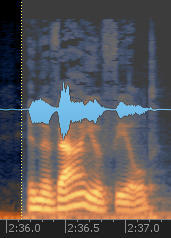
- To find the best settings for your signal quickly, find about five seconds of audio that starts with noise and has both direct signal and reverberant tails.
- If you can find enough direct signal and reverberant tails to fill the De-reverb signal trace meter while using Learn, you will probably get a good reverb profile.
- If you can find enough direct signal and reverberant tails to fill the De-reverb signal trace meter while using Learn, you will probably get a good reverb profile.
- Direct signal, reverberant tail, and noise are all important to help De-reverb understand your audio and set its controls appropriately. It needs to understand the ratio of dry signal to reverberant signal, how long reverb tails last, and where the noise floor of your signal is (to avoid excessive processing).
- If you have trouble getting good results from the Learn feature, you can try:
- learning on transient broadband audio, like drums, claps, or coughs
- learning on any audio that is obviously reverberant
- learning for a longer amount of time. Most reverb can be analyzed in a few seconds, but some reverb profiles can require up to ten seconds of analysis.
- learning on transient broadband audio, like drums, claps, or coughs
- Does De-reverb processing sound unnatural?
- If the output of De-reverb sounds unnatural after Learning, try slowly decreasing the reduction control.
- If the output of De-reverb sounds unnatural after Learning, try slowly decreasing the reduction control.
Visual Example of De-reverb processing
De-reverb has the effect of sharpening a signal in time. You can see this transition in the spectrogram: reverberant audio looks blurred, and cleaned audio appears more focused.
Here, a recording of a distant speaker (left) has had its long tails processed (center) before another De-reverb pass with shorter tail lengths to tackle the early reflections (right):
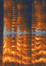
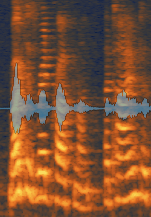
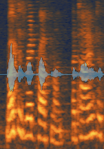
Tips for dealing with complicated reverbs
If the audio you are working with has a very complex reverb, such as a reverb with apparent early reflections, you may get better results after trying a few passes of De-reverb.
- First, start by training the De-reverb and set the Reduction amount to a value that yields good results on the long reverberant tail.
- After processing, Learn a new reverb profile and try reducing the level of early reflections: set the Tail Length control to 0.5, Artifact Smoothing around 3.0, and increase Reduction.
- A combination of De-reverb and Spectral De-noise can be used to tame very reverberant signals. It does not matter whether you process with De-reverb or Spectral De-noise first.
Alternative Modules
For reverb reduction specifically tailored to dialogue, try using the Dialogue De-reverb module in RX 7 Advanced.
De-rustle [ADV]
| Module & Plug-in (Audiosuite Only) |
|---|
Overview
De-rustle is designed to reduce the noise or “rustle” that is often the result of a lavalier microphone rubbing or brushing against clothing during a recording. This type of noise can vary unpredictably over time and exhibit a wide variety of sonic characteristics from higher frequency “brushing” to lower frequency “thuds,” making it a challenging issue to resolve.
The De-rustle module uses a machine learning algorithm trained on isolated rustle samples, clean dialogue samples and dialogue samples with rustle. When processing, De-rustle leverages the trained data to identify and separate the rustle from the dialogue.
Controls
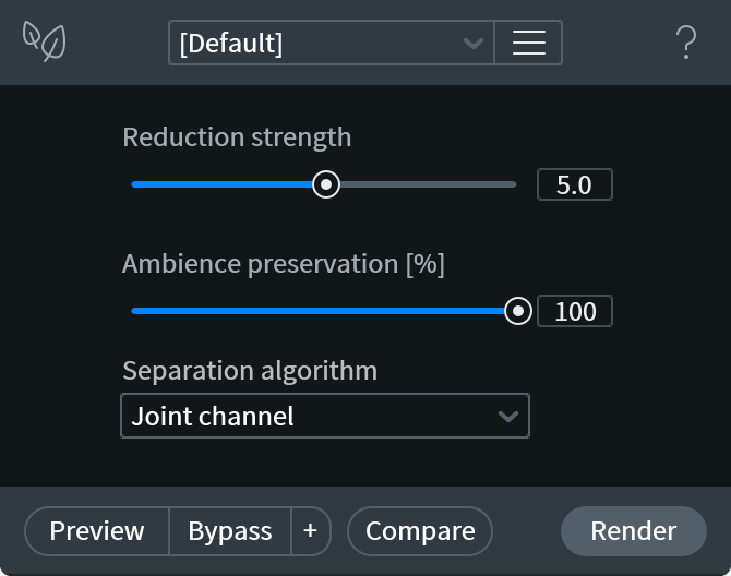
Reduction Strength
Adjusts how sensitive the separation algorithm is to identifying dialogue in the input signal.
- Lower values allow for broader detection of dialogue in the input signal. This can result in more rustle in the processed signal, but can increase clarity of dialogue in the processed output signal.
- Higher values allow for stricter detection of dialogue in the input signal. This can result in more significant reduction of rustle or lav noise, but can decrease the clarity of dialogue in the processed output signal.
Ambience Preservation
Adjusts the amount of background noise to retain in the processed output. The separation algorithm may include background noise and ambience in the signal it has detected as rustle. This can result in unwanted reduction of unrelated background noise in the processed signal.
- Lower values allow for broader detection and separation of rustle against other background noise in the input signal. This can result in more background noise being included and reduced with the separated rustle component.
- Higher values allow for stricter detection and separation of rustle against other background noise in the input signal. This can result in less background noise being included and reduced with the separated rustle component.
Separation Algorithm
The following separation algorithm modes are available in the De-rustle module.
Channel Independent
When this mode is selected, the separation algorithm is applied to the input audio channels independently. Channel independent mode is the fastest Separation algorithm option. It offers the most efficient real-time preview performance and processing speeds when working with the De-rustle module in the RX Audio Editor.
Joint Channel
When this mode is selected, joint channel processing is applied to the input audio before determining the separation between dialogue and rustle signal components. Joint Channel mode offers higher quality separation results than Channel Independent mode, especially when processing stereo files with similar content on both channels (correlated signals, strong stereo image).
Advanced Joint Channel
When this mode is selected, joint channel and additional advanced processing is applied to the input audio before determining separation between dialogue and rustle. Advanced Joint Channel mode offers the highest quality separation results, especially when processing files with high sampling rates. This mode requires longer processing times than the other two modes. If processing time is a concern, Channel Independent mode can be used as a faster, lower quality alternative.
Preview Functionality
Reduced Quality Preview Mode
Unlike many of the modules with preview capabilities in the RX 7 Audio Editor, the De-rustle module utilizes a reduced quality preview mode. Learn more about Reduced Quality Preview Mode.
No Preview in Audiosuite
The RX 7 De-rustle Audiosuite plug-in does not include the ability to preview processing before rendering.
De-wind [ADV]
Overview
De-wind removes intermittent low frequency rumble that can occur when light to moderate bursts of wind come into contact with a microphone diaphragm. De-wind is not designed to remove heavy wind bursts that blow out and distort a microphone signal.
Controls
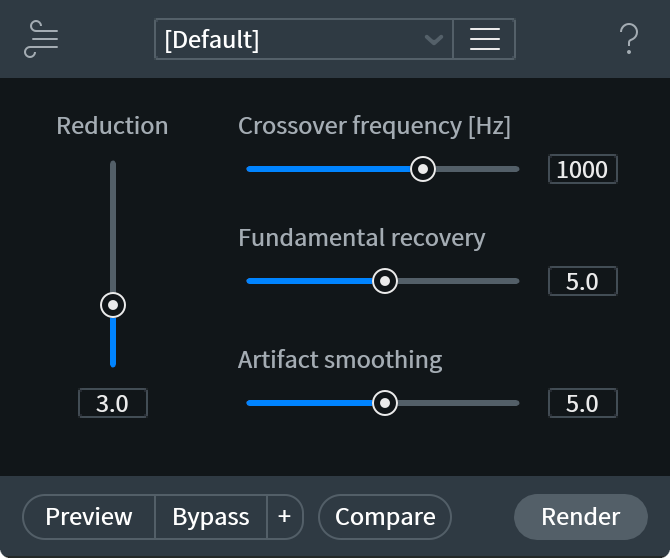
Reduction
Determines the balance between the depth of wind reduction and the preservation of the original signal.
Crossover Frequency
Sets the upper frequency limit for the De-wind processing algorithm.
Fundamental Recovery
Re-synthesizes lower voice harmonics that may be lost or obscured by wind.
Artifact Smoothing
Eliminates “musical noise” that is often characteristic of FFT-based processing. Musical noise can be described as how something may sound underwater. Increase this slider if your output sounds watery, but decrease it when too much smoothing makes speech sound muffled.
What is an FFT?
- Fast Fourier Transform: a procedure for the calculation of a signal frequency spectrum. The greater the FFT size, the greater the frequency resolution, i.e., notes and tonal events will be clearer at larger sizes. However, when using FFT-based processing, the more audio you remove from your source, the more likely you are to create undesirable artifacts.
Tips
When to use the De-wind Module
The De-wind module is best suited to remove and reduce intermittent wind noise in the foreground (for example, a recording with periodic wind gusts that come into direct contact with the diaphragm of the microphone) as opposed to constant wind noise in the background.
The De-wind algorithm attempts to preserve the noise floor of a recording by tracking how it changes over time. Specifically, De-wind is looking for noise floor changes that are characteristic of the noise introduced when a burst of wind comes in contact with the diaphragm of a microphone. If the wind in your recording is constant or in the background, De-wind will treat it as part of the desirable noise floor and will preserve it rather than remove it.
Alternative Modules
For recordings with constant or background wind noise, you may achieve better results by:
- Using the Spectral De-noise module.
- Running De-wind processing more than once.
Deconstruct [ADV]
Overview
Deconstruct analyzes your audio selection and separates the signal into Tonal, Noisy, and Transient (optionally) audio components. The separate components of the signal can then be cut or boosted individually using their associated Gain control.
Controls
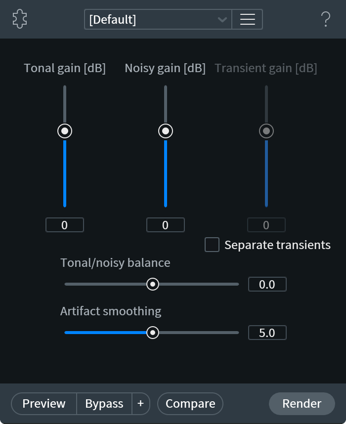
Tonal Gain
Adjusts the level of the tonal components of the signal. Boosting a tonal signal (voice or instrumental) can help lift it out of a noise floor.
Noisy Gain
Adjusts the level of noisy components of the signal. This can be very useful for highlighting areas of raspiness or distortion only, and then attenuating the noisy gain to reduce overall distortion.
Separate Transients
Enables transient separation processing and activates the Transient Gain control.
Transient Gain
Adjusts the level of transient components of the signal. This can work as a transient shaper or a declicker, allowing you to attenuate or boost clicks and attacks.
Transient Separation Performance Note
- The Separate Transients option allows you to control the level of transients, but incurs additional CPU load.
- Increased CPU load may impact the performance of Preview, in this case, using the Compare functionality instead of Preview is a recommended alternative.
Tonal/Noisy Balance
Modifies the default weighting of the separation algorithm used by Deconstruct to categorize components of a signal as either “noisy” or “tonal.”
- Negative values (Tonal weighting) will classify more of the “noisy” components of a signal as “tonal” components and apply Tonal Gain to them during processing.
- Positive values (Noisy weighting) will classify more of the “tonal” components of a signal as “noisy” components and apply Noisy Gain to them during processing.
Artifact Smoothing
Reduces “musical noise” artifacts that are often characteristic of FFT-based processing. Increase this slider if Deconstruct’s output sounds watery, but decrease it when too much smoothing reduces the separation between signal components.
What is an FFT?
- Fast Fourier Transform: a procedure for the calculation of a signal frequency spectrum. The greater the FFT size, the greater the frequency resolution, i.e., notes and tonal events will be clearer at larger sizes. However, when using FFT-based processing, the more audio you remove from your source, the more likely you are to create undesirable artifacts.
More Information
- Deconstruct can be useful for a variety of audio files and applications, particularly when attempting to remove noise that varies throughout the length of a file.
- Deconstruct differs from the Spectral De-noise and Voice De-noise modules, which separate signal from noise based purely on amplitude. Deconstruct analyzes the harmonic structure of a signal independently of level. It does not matter if a tonal signal like hum is quiet or prominent. Deconstruct will treat it as a tonal component and adjust its gain accordingly.
- Deconstruct can be effective in removing residual vinyl noise that may be present after applying De-click or De-crackle processing. Using Deconstruct in this situation may produce better results than using the Spectral De-noise or Voice De-noise modules.
Dialogue Contour [ADV]
Overview
Dialogue Contour allows for the manipulation of the pitch envelope of a dialogue selection. Dialogue Contour features pitch correction processing that is tailored to speech. It is useful for adjusting the inflection of words that may not flow or fit with the rest of the dialogue in the clip.
Displays
Dialogue Contour features a waveform panel and a spectrogram panel that each display information about the current selection in the active file tab. These panels will dynamically update when the selection is changed. If no selection is made in the active file tab, no information will be displayed in the spectrogram or waveform panels.
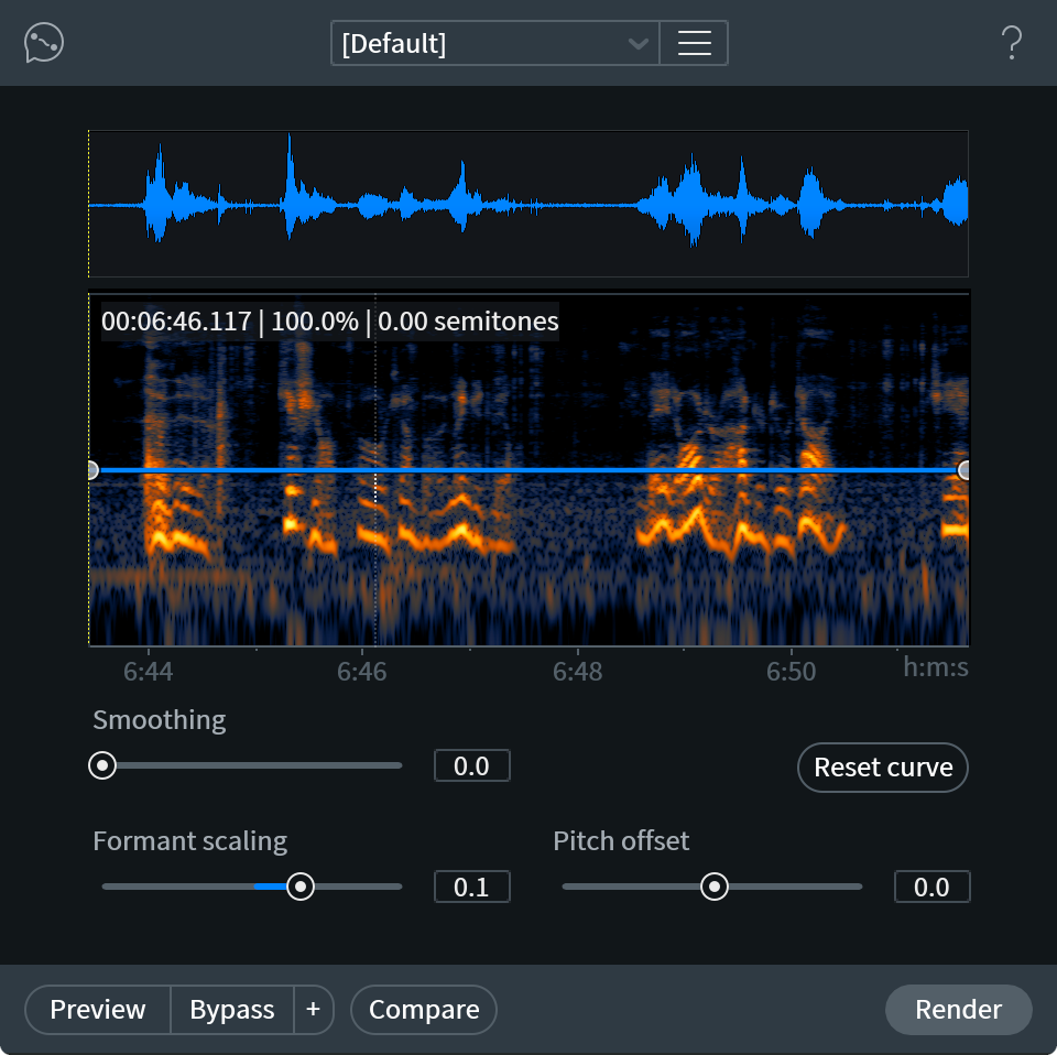
Window Resizing
- Click and drag on the bottom right-hand corner of the module window to customize the window size.
Waveform Display
The single waveform drawn in this panel represents a sum of all enabled channels in the current selection. The waveform drawing is normalized to allow for consistent vertical resolution when working with selections of varying amplitude.

Spectrogram Display
The spectrogram drawn in this panel represents a sum of all enabled channels in the current selection.
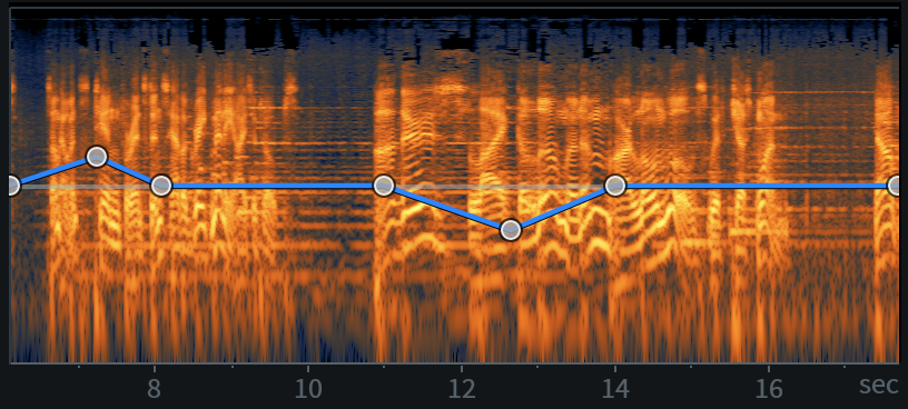
Playhead Indicators
The solid white vertical line and dotted yellow vertical line overlaid on the waveform and spectrogram panels indicate the current playhead position (white) and the playhead anchor position (yellow).
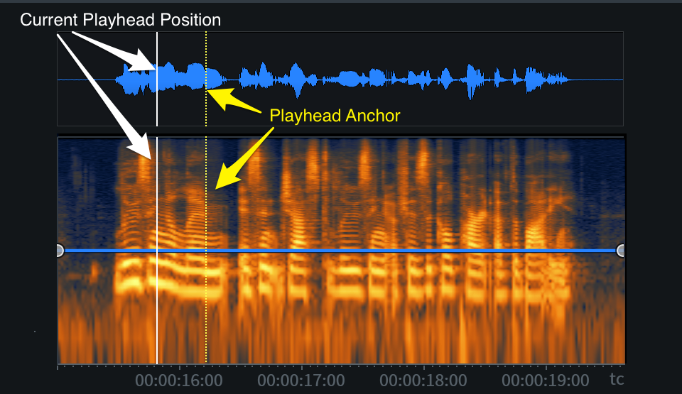
Current Playhead Position
The solid white vertical line overlaid on the waveform and spectrogram panels indicates the current playhead position. This indicator line updates to follow the current playhead position during playback. The playhead position indicator will only appear in the module window when it is within the bounds of the current selection.
Playhead Anchor
The dotted yellow vertical line overlaid on the waveform and spectrogram panels indicates the playhead anchor position in the main editor window. If the playhead anchor position is outside of the current selection bounds, the indicator will not be displayed in the module window.
Contour Curve Display
The blue line overlaid on the spectrogram panel represents the pitch contour curve. Nodes can be added to this curve and adjusted to make changes to pitch over the course of the active selection.

Contour Curve Axes
The contour curve allows for adjustments along two axes: Pitch and Time.
- PITCH: The vertical y-axis of the contour curve represents pitch in semitones.
- The Pitch axis ranges from -6 (bottom) to +6 (top) semitones.
- The center of the Pitch axis equates to 0 semitones.
- The Pitch axis ranges from -6 (bottom) to +6 (top) semitones.
- TIME: The horizontal x-axis represents time.
- The time format used here is determined by the time format display selection in the transport section of the main editor window.
- The range of the time ruler matches the length of the current selection.
- The time format used here is determined by the time format display selection in the transport section of the main editor window.
Ruler Zooming
- Hover over the ruler and use a mousewheel or trackpad to zoom in and out.
- Click and drag left or right on the ruler when zoomed in to change the ruler position.
- Double-click on a ruler display to reset the zoom level to default.
Contour Curve Readout
When the cursor is positioned over the spectrogram panel, a text readout will appear in the upper left hand corner of the panel. This readout displays information about the processing that will be applied when the contour curve is rendered.
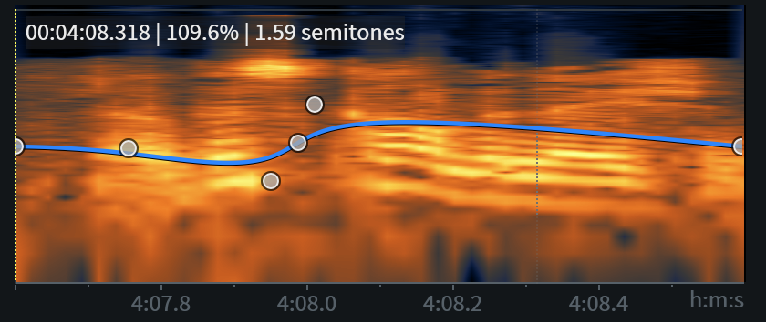
The readout displays the following information about the cursor position, from left to right:
- TIME: Current time position of the cursor within the spectrogram panel.
- PITCH SHIFT (%): Percentage of pitch shift that will be applied at the cursor’s current time position.
- PITCH SHIFT (Semitones): Amount of pitch shift that will be applied at the cursor’s current time position.
Contour Curve Editing
The following section describes the methods and controls available for editing the contour curve.
Add Nodes
Click in the spectrogram panel to add a new node to the contour curve.
Contour Curve Node Limit
- The contour curve supports adding up to 25 nodes.
Semitone Adjustments
Click and drag a node up or down to adjust its semitone value.
Time Adjustments
Click and drag a node left or right to move it earlier or later in time.
Note
- Nodes cannot be moved outside of the time bounds of the current selection.
- The contour curve shape will be maintained when the selection changes.
- The contour curve shape will be maintained after rendering.
Remove Nodes
Individual nodes can be deleted from the curve using the following methods:
- Click and drag a node past the top or bottom edge of the contour curve display to quickly remove it from the curve.
- Control-click (Mac) or ctrl-click (Windows) on a node to remove it from the curve.
Reset Individual Nodes
Double-click on a node to reset it to default (0 semitones).
Reset Curve
Removes all custom nodes from the curve, resetting it to default. Two nodes are present in the default curve, one at the start and one at the end of the current selection. The default nodes are set to 0 semitones (no pitch adjustment).
Smoothing
Adjusts the amount of smoothing applied between nodes on the contour curve. Smoothing is a global control and is applied to all nodes on the curve.
Lower smoothing values: Applies little to no smoothing between nodes on the curve. Allows for stricter transitions between nodes.
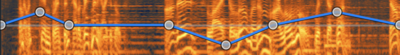
Higher smoothing values: Applies more smoothing between nodes on the curve, resulting in a gradual, rounded slope between points on the curve. Allows for more gradual transitions between nodes.
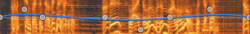
Controls
The following section describes the controls available for refining formant scaling and applying a global pitch offset to the entire selection.
Formant Scaling
Adjusts the amount of formant shift applied when adjusting pitch, the formant shift is scaled relative to the pitch shift. This control can be helpful for maintaining or correcting the timbre and quality of the dialogue after processing. In some situations, the formants may sound unnaturally high or low after processing. Formant scaling can be used to correct for these unnatural sounding results.
Pitch Offset
Applies a global semitone offset value to the current selection. This value is added to or subtracted from the processing applied by the contour curve. Adjusting the Pitch Offset amount will not update the contour curve display.
Tip: Pitch Offset
Pitch Offset can be useful for adjusting a single word by a static amount.
For example, setting Pitch Offset to +2 semitones with the contour curve set to default will shift the pitch of the current selection up by 2 semitones.
Alternative Modules
For more generalized, non-dialogue specific pitch envelope editing, try using the Variable Pitch module. The Variable Pitch module features the ability to shift pitch over the course of a selection with or without preserving timing and is suitable for use on a wide range of input material.
Dialogue Isolate [ADV]
| Module & Plug-in (Audiosuite Only) |
|---|
Overview
Dialogue Isolate is designed to separate spoken dialogue from non-stationary background noise such as: crowds, traffic, footsteps, weather, or other noise with highly variable characteristics. It can be particularly effective at increasing the level of dialogue in challenging low signal-to-noise ratio conditions.
Dialogue Isolate uses a machine learning algorithm (deep neural network) that was trained on a large library of speech and noise data to automatically recognize speech content in an input signal. It leverages this training data to detect and separate dialogue and noise into two separate signal components. The levels of the separated dialogue and noise components can then be independently adjusted using the Dialogue and Noise gain controls.
Controls
The following controls are available in the Dialogue Isolate module:
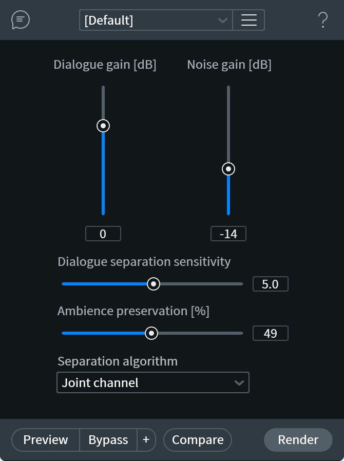
Dialogue Gain
Adjusts the amount of gain (in dB) applied to the components identified as dialogue by the separation algorithm.
Noise Gain
Adjusts the amount of gain (in dB) applied to the components identified as noise by the separation algorithm.
Dialogue Separation Sensitivity
Determines how much of the input signal will be identified as dialogue by the separation algorithm.
- Lower values will instruct the separation algorithm to narrowly define what it categorizes as dialogue in the input signal. This can result in more noise being included in the rendered signal, but can help to maintain dialogue clarity.
- Higher values will instruct the separation algorithm to broadly define what it categorizes as dialogue in the input signal. This can result in more significant noise reduction, at the cost of introducing artifacts and potentially reducing dialogue clarity.
Separation Algorithm
The following separation algorithm modes are available in the Dialogue Isolate module.
Channel Independent
When this mode is selected, the separation algorithm is applied to the input audio channels independently. Channel independent mode is the fastest Separation algorithm option. It offers the most efficient real-time preview performance and processing speeds when working with the Dialogue Isolate module in the RX Audio Editor.
Joint Channel
When this mode is selected, joint channel processing is applied to the input audio before determining the separation between dialogue and noise signal components. Joint Channel mode offers higher quality separation results than Channel Independent mode, especially when processing stereo files with similar content on both channels (correlated signals, strong stereo image).
Advanced Joint Channel
When this mode is selected, joint channel and additional advanced processing is applied to the input audio before determining separation between dialogue and noise. Advanced Joint Channel mode offers the highest quality separation results, especially when processing files with high sampling rates. This mode requires longer processing times than the other two modes. If processing time is a concern, Channel Independent mode can be used as a faster, lower quality alternative.
Preview Functionality
Reduced Quality Preview Mode
Unlike many of the modules with preview capabilities in the RX 7 Audio Editor, the Dialogue Isolate module utilizes a reduced quality preview mode. Learn more about Reduced Quality Preview Mode.
No Preview in Audiosuite
The RX 7 Dialogue Isolate Audiosuite plug-in does not include the ability to preview processing before rendering.
Alternative Modules
For stationary noise, such as hiss, buzz, line noise, etc., Dialogue Isolate may produce satisfactory results, but we also suggest trying the Spectral De-noise module if you are having trouble achieving acceptable results with Dialogue ISolate.
Dialogue De-reverb [ADV]
Overview
Dialogue De-reverb allows for efficient and clean reduction of unwanted reverb in dialogue recordings. Unlike the all-purpose De-reverb module, Dialogue De-reverb does not require learning a reverb profile from the input audio before processing. Instead, it leverages a machine-learning algorithm that has been trained to identify and separate reverberant components from dialogue components in an input signal. After separating the dialogue and reverb components, the reverb signal level can be independently adjusted without reducing the dialogue signal level.
Controls
The following section describes the controls available for reducing the separated reverb level, refining the reverb detection sensitivity, adjusting the amount of background noise to maintain, and determining the separation algorithm behavior.
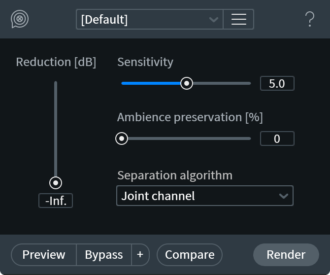
Reduction
Adjusts the amount of negative gain (in dB) applied to the separated reverb component signal.
Sensitivity
Determines how much of the input signal will be identified as reverb by the separation algorithm.
- Lower values will instruct the separation algorithm to narrowly define what it categorizes as reverb in the input signal. This can result in the presence of reverberant content in the rendered signal, but can help to maintain dialogue clarity.
- Higher values will instruct the separation algorithm to broadly define what it categorizes as reverb in the input signal. This can result in more significant reverb reduction, at the cost of introducing artifacts and reducing dialogue clarity.
Ambience Preservation
Adjusts the amount of desired background noise to be retained in the processed output. The separation algorithm may include background noise in the separated reverb signal component, resulting in the unwanted reduction of unrelated background noise.
- Lower values allow for broader detection and separation of reverb against other background noise in the input signal. This may result in unwanted reduction of background noise when reducing the reverb component level.
- Higher values allow for stricter detection and separation of reverb against other background noise in the input signal. This can result in less background noise being included in the separated reverb component, but may result in unwanted reverberant content being identified as background noise.
Separation Algorithm
The following separation algorithm modes are available in the Dialogue De-reverb module.
Channel Independent
When this mode is selected, the separation algorithm is applied to the input audio channels independently. Channel independent mode is the fastest Separation algorithm option. It offers the most efficient real-time preview performance and processing speeds when working with the Dialogue De-reverb module in the RX Audio Editor.
Joint Channel
When this mode is selected, joint channel processing is applied to the input audio before determining the separation between dialogue and reverb signal components. Joint Channel mode offers higher quality separation results than Channel Independent mode, especially when processing stereo files with similar content on both channels (correlated signals, strong stereo image).
Advanced Joint Channel
When this mode is selected, joint channel and additional advanced processing is applied to the input audio before determining separation between dialogue and reverb. Advanced Joint Channel mode offers the highest quality separation results, especially when processing files with high sampling rates. This mode requires longer processing times than the other two modes. If processing time is a concern, Channel Independent mode can be used as a faster, lower quality alternative.
Preview Functionality
Reduced Quality Preview Mode
Unlike many of the modules with preview capabilities in the RX 7 Audio Editor, Dialogue De-reverb utilizes a reduced quality preview mode. Follow this link to learn more about Reduced Quality Preview Mode.
Alternatives Modules
For more generalized, non-dialogue specific reverb reduction, try using the De-reverb module.
Interpolate [STD & ADV]
Overview
The Interpolate module is used for repairing individual clicks below 4000 samples in length. This module corrects clicks by synthesizing a replacement signal based on the content in your selection. It can be used as a substitute for the ‘pencil’ editing tool found in many audio editing applications.
Controls
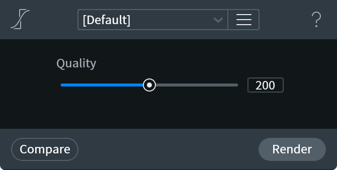
Quality
Adjusts the complexity of the sythesized replacement signal by adjusting the interpolation order. This allows you to tailor the results of the processing to better fit the surrounding audio.
The following images illustrate the effect of Interpolate processing on a selection that is 214 samples in length. The images are zoomed in to illustrate the effect of adjusting the Quality parameter.
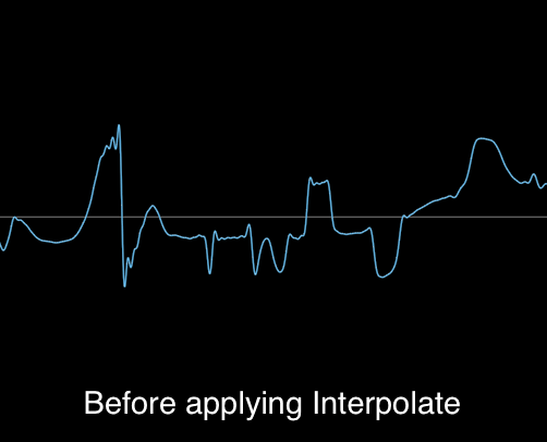
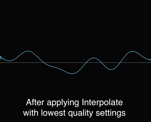
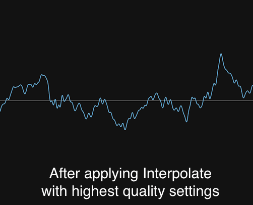
Mouth De-click [STD & ADV]
| Module & Plug-in |
|---|
Overview
Mouth De-click detects and reduces mouth noises such as clicks and lip smacks. It’s designed for use on longer audio selections, but it can also be used to remove individual clicks.
Controls
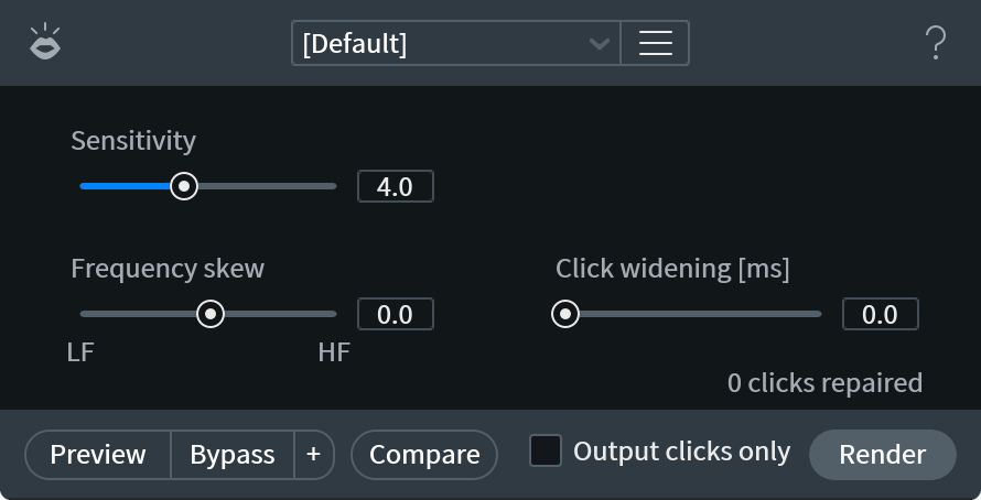
- SENSITIVITY: Determines how many mouth clicks are detected in the signal. Increasing sensitivity can impact plosives, reducing or damaging the original signal.
- FREQUENCY SKEW: Targets the detection and removal of clicks to lower or higher frequencies. Negative values are more suitable for generic clicks such as those found on vinyl recordings. A setting of zero or above targets mouth clicks in the middle frequencies.
- CLICK WIDENING: Click Widening extends the repair area around detected clicks, compensating for mouth sounds such as lip smacks that have a decay.
More Information
Running Mouth De-click twice sometimes produces a better result than a single pass. This is because an initial run can miss the quieter clicks that were masked by louder clicks.
Music Rebalance [STD & ADV]
| Module & Plug-in (Audiosuite Only) |
|---|
Overview
Music Rebalance leverages a machine learning algorithm trained to identify and separate the following elements in a mix: Voice, Bass, and Percussion. Any content that is not otherwise identified as Voice, Bass or Percussion will be categorized as Other. The level of each mix element can be independently adjusted after separation.
Music Rebalance can be useful for adjusting the level of a particular mix element when the original tracks or stems are not available as an alternative solution. In some cases, it can also be used to isolate a single mix element (e.g. the lead vocal) by reducing the level of the other three mix elements. It is available as a module in the RX 7 Audio Editor and as an Audiosuite plug-in (AAX & DPM) in Pro Tools.
Controls
The following section describes the controls available for adjusting levels, refining mix element separation, and determining the global separation algorithm mode.
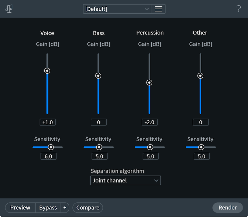
Note: Sensitivity Controls
The Sensitivity controls for each mix element work relative to one another. For example, setting all sensitivity controls to a value of 5.0 has the same effect as setting all sensitivity controls to a value of 8.0.
Voice
- Gain: Adjusts the level (in dB) of the separated Voice signal.
- Sensitivity: Determines how much of the input signal will be identified as Voice by the separation algorithm.
- Lower values will instruct the separation algorithm to narrowly define what it considers to be vocal content in the input signal. The resulting signal will contain less audible “bleed” from the other mix elements at the cost of introducing watery, unnatural sounding artifacts and reduced vocal clarity.
- Higher values will instruct the separation algorithm to broadly define what it considers to be vocal content in the input signal. The resulting signal will contain more audible “bleed” from the other mix elements (e.g. percussive content leaking into the voice signal.) However, the bleed from the other mix elements can help to reduce the unnatural artifacts and lack of clarity that can occur at lower sensitivity values.
- Lower values will instruct the separation algorithm to narrowly define what it considers to be vocal content in the input signal. The resulting signal will contain less audible “bleed” from the other mix elements at the cost of introducing watery, unnatural sounding artifacts and reduced vocal clarity.
Bass
- Gain: Adjusts the level (in dB) of the separated Bass signal.
- Sensitivity: Determines how much of the input signal will be identified as Bass by the separation algorithm.
- Lower values will instruct the separation algorithm to narrowly define what it considers to be bass in the input signal. The resulting signal will contain less audible “bleed” from the other mix elements, at the cost of introducing unnatural, watery sounding artifacts and reduced clarity.
- Higher values will instruct the separation algorithm to broadly define what it considers to be bass in the input signal. The resulting signal will contain more audible “bleed” from the other mix elements (e.g. percussive content leaking into the bass signal.) However, the “bleed” from the other mix elements can help to reduce the unnatural artifacts and lack of clarity that can occur at lower sensitivity values.
- Lower values will instruct the separation algorithm to narrowly define what it considers to be bass in the input signal. The resulting signal will contain less audible “bleed” from the other mix elements, at the cost of introducing unnatural, watery sounding artifacts and reduced clarity.
Percussion
- Gain: Adjusts the level (in dB) of the separated Percussion signal.
- Sensitivity: Determines how much of the input signal will be identified as Percussion by the separation algorithm.
- Lower values will instruct the separation algorithm to narrowly define what it considers to be percussion in the input signal. The resulting signal will contain less audible “bleed” from the other mix elements, at the cost of introducing unnatural, watery sounding artifacts and reduced clarity.
- Higher values will instruct the separation algorithm to broadly define what it considers to be percussion in the input signal. The resulting signal will contain more audible “bleed” from the remaining mix elements (e.g. vocal content leaking into the percussion signal.) However, this “bleed” signal can help to reduce the unnatural artifacts and lack of clarity that can occur at lower sensitivity values.
- Lower values will instruct the separation algorithm to narrowly define what it considers to be percussion in the input signal. The resulting signal will contain less audible “bleed” from the other mix elements, at the cost of introducing unnatural, watery sounding artifacts and reduced clarity.
Other
- Gain: Adjusts the level (in dB) of the signal separated into the Other mix element.
- Sensitivity: Determines how much of the input signal will be categorized as something other than Voice, Bass, or Percussion by the separation algorithm.
- Lower values will instruct the separation algorithm to narrowly define the content that is not included in the 3 main mix elements. The resulting signal will contain less audible “bleed” from the 3 main mix elements in the separated Other element, at the cost of introducing unnatural or watery sounding artifacts and reduced clarity.
- Higher values will instruct the separation algorithm to broadly define the content that is not included in the 3 main mix elements. The resulting signal will contain more audible “bleed” from the main mix elements. However, this “bleed” signal can help to reduce unnatural artifacts and reduced clarity that can occur at lower sensitivity values.
- Lower values will instruct the separation algorithm to narrowly define the content that is not included in the 3 main mix elements. The resulting signal will contain less audible “bleed” from the 3 main mix elements in the separated Other element, at the cost of introducing unnatural or watery sounding artifacts and reduced clarity.
Separation Algorithm
The following separation algorithm modes are available in the Music Rebalance module.
Channel Independent
When this mode is selected, the separation algorithm is applied to the input audio channels independently. Channel independent mode is the fastest Separation algorithm option. It offers the most efficient real-time preview performance and processing speeds when working with the Music Rebalance module in the RX Audio Editor.
Joint Channel
When this mode is selected, joint channel processing is applied to the input audio before determining mix element separation. Joint Channel mode offers higher quality separation results than Channel Independent mode, especially when processing stereo files with similar content on both channels (correlated signals, strong stereo image).
Advanced Joint Channel
When this mode is selected, joint channel and additional advanced processing is applied to the input audio before determining mix element separation. Advanced Joint Channel mode offers the highest quality separation results, especially when processing files of high sampling rates or when processing musical content that was not tuned to an A440 scale. This mode requires longer processing times than the other two modes. If processing time is a concern, Channel Independent mode can be used as a faster, lower quality alternative.
Preview Functionality
Reduced Quality Preview Mode
Unlike many of the modules with preview capabilities in the RX 7 Audio Editor, Music Rebalance utilizes a reduced quality preview mode. Follow this link to learn more about Reduced Quality Preview Mode.
Note about Music Rebalance Audiosuite Plug-in
No Preview in Audiosuite
The RX 7 Music Rebalance Audiosuite plug-in does not include the ability to preview processing before rendering.
Spectral De-noise [STD & ADV]
| Module & Plug-in |
|---|
Overview
Spectral De-noise is designed to remove stationary or slowly changing tonal noise and broadband hiss by learning a profile of the offending noise and then subtracting it from the signal. It can be useful for tape hiss, HVAC systems, outdoor environments, line noise, ground loops, camera motors, fans, wind, and complex buzz with many harmonics.
Spectral De-noise learns a profile of the background noise, then subtracts that noise when a signal’s amplitude drops below the specified threshold. It is a flexible tool that can be used to quickly achieve accurate, high-quality noise reduction. It also provides separate controls for tonal and broadband noise, management of denoising artifacts, and an editing interface for controlling reduction across the frequency spectrum.
Controls
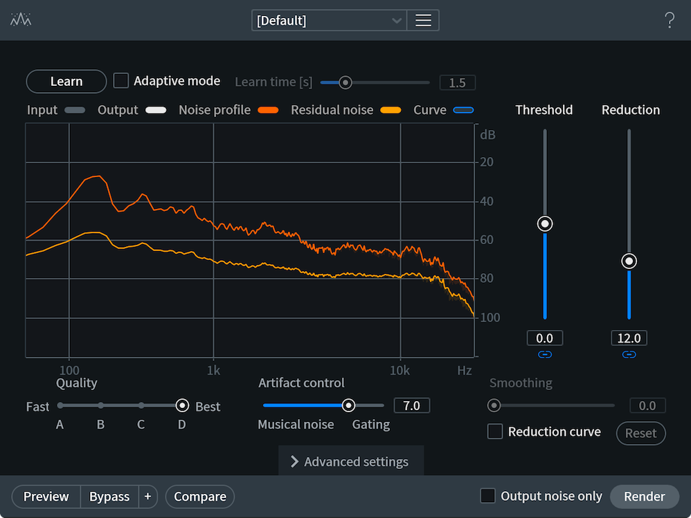
Learn
When Learn is enabled, Spectral De-noise will capture a noise profile from your selection. After a noise profile is captured using Learn, it remains fixed for the duration of processing. Manually learned noise profiles are best suited to removing or reducing noise that is constant and continuous throughout the duation of the file.
How to Learn a noise profile in Spectral De-noise
- Make a selection of the longest section of noise you can find in your file (ideally a few seconds in length)
- Click the Learn button to capture a noise profile.
- To capture a noise profile in the RX Audio Editor Spectral De-noise module, make a selection and click “Learn”
- To capture a noise profile in the RX Spectral De-noise plug-in, engage the Learn button and playback audio, OR choose “Preview” in Audiosuite to capture the noise profile from your current selection.
- To capture a noise profile in the RX Audio Editor Spectral De-noise module, make a selection and click “Learn”
More Information about Learning Noise Profiles
See the More Information section below to learn more about getting the best results when capturing a noise profile and Learning a noise profile from multiple selections in the RX 7 Audio Editor.
Adaptive Mode
When Adaptive Mode is enabled, the noise profile used for Spectral De-noise processing will change based on the incoming audio. Adaptive mode can work well with noise sources that are constantly changing, like recordings in outdoor environments, traffic noise, or ocean waves.
Spectral De-noise Adaptive mode Performance Note
Adaptive mode in Spectral De-noise uses a significant amount of memory and computational power. For a more efficient form of adaptive noise reduction, try the Adaptive mode in Voice De-noise, which is designed to be highly efficient and zero-latency.
Learning Time [s]
Determines the amount of lookahead time used by Adaptive mode when learning noise profiles that change over time.
Threshold (Noisy/Tonal)
Controls the amplitude separation of noise and useful signal levels.
- Higher threshold settings reduce more noise, but also suppress low-level signal components.
- Lower threshold preserves low-level signal details, but can result in noise being modulated by the signal. Threshold elevation can be done separately for tonal and random noise parts. A good default is 0 dB.
Tip
If background noise changes in amplitude over time (like traffic noise or record surface noise), raise the Threshold to accommodate for the changes.
Reduction (Noisy/Tonal)
Controls the desired amount of noise suppression in decibels. Spectral De-noise can automatically separate noise into tonal parts (such as hum, buzz or interference) and random parts (such as hiss). You can specify the amount of suppression for these parts separately (e.g. in some situations it can be desirable to reduce only unpleasant buzz while leaving unobjectionable constant hiss).
Note
Strong suppression of noise can also degrade low-level signals, so it is recommended to apply only as much suppression as needed for reducing the noise to levels where it becomes less objectionable.
Quality
Affects the quality and computational complexity of the noise reduction. This selection directly affects CPU usage. RX’s Spectral De-noise module offers four algorithms that vary in processing time.
- A: is the least CPU intensive process and is suitable for real-time operation. It reduces musical noise artifacts by time smoothing of the signal spectrum.
- B: achieves more advanced musical noise suppression by using adaptive 2D smoothing (both time and frequency). It is more CPU intensive and has more latency, but can still run in real-time on most machines.
- C: adds multiresolution operation for better handling of signal transients and even fewer musical noise artifacts. It is a very CPU intensive algorithm and can only run in real-time on faster multicore machines.
- D: adds high-frequency synthesis for reconstruction of signal details buried in noise. The speed of algorithm D is similar to algorithm C.
Artifact Control
Determines how much noise reduction will depend upon either spectral subtraction or wide band gating.
- When using lower values, noise reduction will rely on spectral subtraction. This can more accurately separate noise from the desired audio signal, but can produce musical noise artifacts, resulting in a “chirpy” or “watery” sound during heavy processing.
- When using higher values, the noise reduction will rely more heavily upon wider band gating which will have fewer musical noise artifacts, but sound more like broadband gating, resulting in bursts of noise right after the signal falls below the threshold.
Noise Spectrum Display
The Noise Spectrum display shows useful information during both playback and when the noise reduction process is being applied.
- Noise Spectrum Color Legend
- Input (Gray): spectrum of input audio signal
- Output (White): spectrum of the denoised output audio signal
- Noise Profile (Orange): the learned noise profile plus offset from the Threshold control
- Residual Noise (Yellow): desired noise floor after denoising, can be controlled by modifying the Reduction Curve
- Reduction Curve (Blue): manual weighting of the noise reduction across the spectrum
- Input (Gray): spectrum of input audio signal
Smoothing
When the Reduction Curve is enabled, this controls the amount of interpolation between your reduction curve points, allowing for sharper or more gradual slopes between edit curve points.
Reduction Curve
When enabled, allows for fine tuning of the reduction spectrum with up to 25 edit points. This enables you to customize the amount of noise reduction being applied across different frequency regions.
- Higher edit point values result in less noise reduction in the associated frequency region.
- Lower edit point values result in more noise reduction in the associated frequency region.
- For example, if you wanted to reduce some low HVAC rumble but preserve some energy in higher frequencies, you could drag the curve’s leftmost point down a little bit, then create a point around 5 kHz and drag it up a bit.
Interacting with the Reduction Curve Edit points
- Add an edit point: left-click, displayed as gray box along envelope curve
- Remove an edit point: right-click or drag it outside the screen
- You can axis-lock reduction curve points by holding Shift while dragging them, and get very fine control over positioning by holding Control/Command.
Reset
Returns the Noise Reduction Curve to its default setting of 0dB.
Advanced Settings
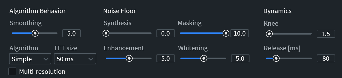
Algorithm Behavior (Advanced Settings)
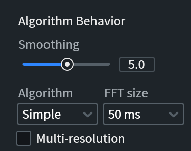
Smoothing
Controls the reduction of musical noise artifacts which can be a result of heavy denoising.
What is musical noise?
Musical noise is caused by random statistical variations of noise spectrum that cause random triggering of sub-band gates. These artifacts are sometimes described as “chirpy” or “watery” sounds left behind during the noise reduction process.
Algorithm
Selects the smoothing algorithm for the removal of random ripples (“musical noise” artifacts) that can occur in the spectrogram when processing your audio. The strength of smoothing is controlled by the Smoothing slider.
- SIMPLE: Performs independent noise gating in every frequency channel of FFT. Release time of sub-band gates is controlled by the Release slider. This is a fast algorithm with low latency that is suitable for real-time operation.
- ADVANCED & EXTREME: Perform joint time-frequency analysis of the audio signal which results in better quality and fewer “musical noise” artifacts. These algorithms have higher latency and computational complexity.
FFT Size (ms)
Selects the time and frequency resolution of the processing.
- Higher FFT sizes give you more frequency bands allowing you to cut noise between closely spaced signal harmonics, or cut steady-state noise harmonics without affecting adjacent signals.
- Lower FFT sizes allow for faster response to changes in the signal and produce fewer noisy echoes around transient events.
Re-learn your Noise profile if you change FFT size
Whenever the FFT size is changed, it is recommended that you run the De-noise module’s Learn feature again because the old noise profile was taken at a different FFT size and therefore becomes inaccurate.
Multi-Res
Enables multi-resolution processing for the selected algorithm type. When you select the Multi-res checkbox, the signal is analyzed in real-time and the most appropriate FFT size is chosen for each segment of the signal. This is done to minimize the smearing of transients and at the same time achieve high frequency resolution where it is needed.
Note
The FFT size control does not have any effect in multi-resolution mode as the FFT resolution is selected automatically. The noise profile does not need to be re-learned when switching to multi-resolution mode.
What is an FFT?
Fast Fourier Transform: a procedure for the calculation of a signal frequency spectrum. The greater the FFT size, the greater the frequency resolution, i.e., notes and tonal events will be clearer at larger sizes. However, when using FFT-based processing, the more audio you remove from your source, the more likely you are to create undesirable artifacts.
Noise Floor (Advanced Settings)
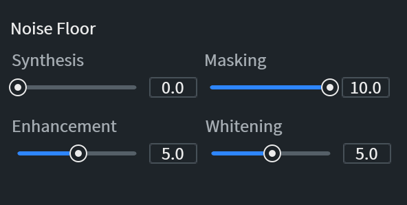
- Synthesis
Synthesizes high frequency material after denoising.
- When Synthesis is set to a value greater than zero, signal harmonics are synthesized after denoising. The synthesized harmonics remain at the level of the noise floor, and serve to fill in gaps in high frequencies caused by processing.
Increasing Synthesis can increase the sense of life and air in processed audio. Too much Synthesis may cause apparent distortion in the signal.
ENHANCEMENT: Enhances signal harmonics that fall below the noise floor.
- Enhancement predicts a signal’s harmonic structure and places less noise reduction in areas where possible signal harmonics could be buried in noise. This aids in preserving high-frequency signal harmonics that may be buried and not detected otherwise.
- Enhancement can make the resulting signal brighter and more natural sounding, but high values of harmonic enhancement can also result in high-frequency noise being modulated by the signal.
- Enhancement predicts a signal’s harmonic structure and places less noise reduction in areas where possible signal harmonics could be buried in noise. This aids in preserving high-frequency signal harmonics that may be buried and not detected otherwise.
MASKING: Reduces the depth of noise reduction where you wouldn’t perceive any effect from it.
- Masking enables a psychoacoustic model that dynamically controls suppression amount to facilitate the use of softer suppression where noise is subjectively inaudible. When noise in certain regions is calculated to be inaudible, this feature prevents any signal processing in these regions. This potentially reduces the amount of processing done to the signal and may positively affect overall signal integrity. The position of the slider controls the influence of psychoacoustic model on suppression levels.
- If you need to cut very high, inaudible frequencies, set this to 0. Otherwise, leave this at 10.
- Masking enables a psychoacoustic model that dynamically controls suppression amount to facilitate the use of softer suppression where noise is subjectively inaudible. When noise in certain regions is calculated to be inaudible, this feature prevents any signal processing in these regions. This potentially reduces the amount of processing done to the signal and may positively affect overall signal integrity. The position of the slider controls the influence of psychoacoustic model on suppression levels.
Note
When the Masking slider is set to 0, the feature is turned off, and the amount of noise suppression is uniformly governed to the yellow curve in spectrum analyzer (more precisely — by the difference between the yellow curve and orange curve).
- WHITENING: Shapes the noise floor after processing to be more like white noise. Whitening modifies the amount of noise reduction (shown by the yellow curve) applied at different frequencies to shape the spectrum of the residual noise.
- When Whitening is set to zero, the suppression is uniform at all frequencies, as controlled by Reduction (tonal/broadband) sliders, and the suppressed noise has a similar spectral shape to the original noise.
- When Whitening is set to the maximum value, the desired shape of suppressed noise floor is made close to white noise, so that residual noise has more neutral sound.
Understanding the effect of the Whitening control
Changing the noise floor balance with Whitening can help prevent gaps from over-processing, but an unnaturally white noise floor can introduce problems like noise modulation when editing or mixing with other noises from a unique space (like a set location.)
- When Whitening is set to zero, the suppression is uniform at all frequencies, as controlled by Reduction (tonal/broadband) sliders, and the suppressed noise has a similar spectral shape to the original noise.
Dynamics (Advanced Settings)
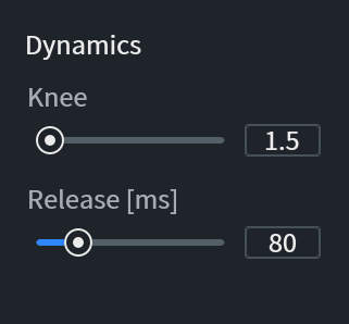
- KNEE: Controls how surgical the algorithm’s differentiation is between the signal and noise. This slider controls the sharpness of the gating knee in the denoising process.
- At higher values, transitions in the De-noise are more abrupt and can become prone to errors in the detection of the signal with respect to the noise.
- At lower values, the denoising becomes more forgiving around the knee, and applies less attenuation to signals that are only slightly below the threshold. This may result in a lower depth of noise reduction, but can also have fewer artifacts.
- At higher values, transitions in the De-noise are more abrupt and can become prone to errors in the detection of the signal with respect to the noise.
- RELEASE [ms]: Selects the release time of sub-band noise gates in milliseconds. Longer release times can result in less musical noise, but may also reduce or soften the signal’s initial transients or reverb tails after the signal’s decay.
Note
The Release control is only available when the Simple algorithm is selected.
More Information
Tips for getting the best results when learning noise profiles manually
- Before learning a noise profile, identify and select the longest section (ideally a few seconds in length) of the recording that contains only the noise you wish to remove or reduce.
- To ensure the best results, your selection should not contain any content that you wish to preserve (for example, do not include any audio you do not consider to be “noise” in your selection.)
- Usually you can find noise only sections at the beginning or end of a file, or during a pause or break in the recording (for example, a pause between words in dialogue recordings.)
Learning a Noise Profile From Multiple Selections
In the RX standalone application, it is possible to create a spectral profile from multiple isolated selections. This is useful when you have a file where it’s impossible to find enough isolated noise to build the profile.
For example, if you are trying to restore a file where someone is speaking over noise, you can select noise in frequencies where none of the voice is present at a given time. If you select enough of this noise with the Lasso or Brush selection tools, you can create an accurate noise profile that will give you good results with Spectral De-noise. You can create more than one selection at a time by holding Shift while making a selection.
Select noise anywhere you can to build a better noise profile.
This feature is not available in the Spectral De-noise plug-in because it requires using RX’s spectral selection tools as well as accurate calculation of the time and frequency of the selected areas.
If you are unable to create a full noise profile with multiple selections, RX can try to build a reasonable noise profile out of your existing profile. If you have an incomplete noise profile, RX will ask you if you want it to complete the profile.
For example, if you can only capture a low frequency rumble below 100 Hz, some broadband noise between 200 Hz and 5000 Hz, and all the noise above 8000 Hz, RX can fill in the gaps for you.
Building a profile from multiple selections gives you some flexibility, and RX will guess any noise you missed.
Spectral Repair [STD & ADV]
Overview
Spectral Repair intelligently removes undesired sounds from a file with natural-sounding results.
This tool treats selections within the spectrogram/waveform display as corrupted audio that will be repaired using information from outside of the selection.
Select the noise you want to repair and Spectral Repair will reduce it to the level of the noise floor, replace it with audio from around the selection, or generate entirely new audio to fit the selection.
Attenuate
This mode removes sounds by comparing the content inside of a selection to the content outside of the selection. Attenuate reduces spectrogram magnitudes in the selected area to match magnitudes from the surrounding area, resulting in the removal of the sound without leaving an audible gap behind. Attenuate does not resynthesize any audio. It modifies dissimilar audio in your selection to be more similar to the surrounding audio.
Attenuate is suitable for recordings with background noise or where noise is the essential part of music (drums, percussion) and should be accurately preserved. It’s also good when unwanted events are not obscuring the desired signal completely. For example, Attenuate can be used to bring noises like door slams or chair squeaks down to a level where they are inaudible and blend into background noise.
Controls
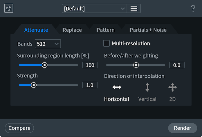
- BANDS: Selects the number of frequency bands used for interpolation.
- A higher number of bands can provide better frequency resolution, but also requires wider surrounding area to be analyzed for interpolation.
- A lower number of bands is ideal for processing short selections or transient signals.
- A higher number of bands can provide better frequency resolution, but also requires wider surrounding area to be analyzed for interpolation.
- SURROUNDING REGION LENGTH: Defines how much of the surrounding content will be used for interpolation.
- STRENGTH: Adjusts strength of attenuation.
- MULTI-RESOLUTION: The multi-resolution mode allows for better frequency resolution for the interpolation of low-frequency content and better time resolution for the interpolation of high-frequency content.
- BEFORE/AFTER WEIGHTING: Gives more weight to the surrounding audio before or after the selection.
- DIRECTION OF INTERPOLATION: Determines where the material used in the repair process is located in relation to the current selection.
- HORIZONTAL: Signal to the left and right of the current selection will be used for interpolation.
- VERTICAL: Signal above and below the current selection will be used for interpolation.
- 2D: Signal above, below, to the left and to the right of the current selection will be used for interpolation.
Note: Direction Of Interpolation control availability
- Replace, Pattern and Partials + Noise tabs only utilize Horizontal mode and do not display this option.
- Replace, Pattern and Partials + Noise tabs only utilize Horizontal mode and do not display this option.
- HORIZONTAL: Signal to the left and right of the current selection will be used for interpolation.
Replace
The Replace tab can be used to replace badly damaged sections (such as gaps) in tonal audio. It completely replaces the selected content with audio interpolated from the surrounding data.
Controls
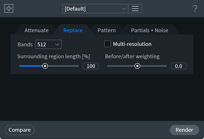
- BANDS: Selects the number of frequency bands used for interpolation.
- A higher number of bands can provide better frequency resolution, but also requires wider surrounding area to be analyzed for interpolation.
- A lower number of bands is ideal for processing short selections or transient signals.
- A higher number of bands can provide better frequency resolution, but also requires wider surrounding area to be analyzed for interpolation.
- SURROUNDING REGION LENGTH: Defines how much of the surrounding content will be used for interpolation.
- MULTI-RESOLUTION: The multi-resolution mode allows for better frequency resolution for the interpolation of low-frequency content and better time resolution for the interpolation of high-frequency content.
- BEFORE/AFTER WEIGHTING: Gives more weight to the surrounding audio before or after the selection.
Pattern
This mode finds the most similar portion of the surrounding audio and uses this to replace the corrupted audio.
Pattern mode is suitable for badly damaged audio with background noise or for audio with repeating parts.
Controls
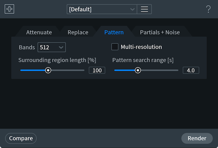
- BANDS: Selects the number of frequency bands used for interpolation.
- A higher number of bands can provide better frequency resolution, but also requires wider surrounding area to be analyzed for interpolation.
- A lower number of bands is ideal for processing short selections or transient signals.
- A higher number of bands can provide better frequency resolution, but also requires wider surrounding area to be analyzed for interpolation.
- SURROUNDING REGION LENGTH: Defines how much of the surrounding content will be used for interpolation.
- MULTI-RESOLUTION: The multi-resolution mode allows for better frequency resolution for the interpolation of low-frequency content and better time resolution for the interpolation of high-frequency content.
- PATTERN SEARCH RANGE: Selects the length of the audio segment used in a search for a suitable replacement interval. For example, setting it to 5 seconds will allow search within ±5 second range from the selection.
Partials and Noise
The advanced version of Replace mode. It restores harmonics of the audio more accurately with control over the Harmonic sensitivity parameter.
This mode allows for higher-quality interpolation by explicit location of signal harmonics from the 2 sides of the corrupted interval and linking them together by synthesis.
Partials + Noise is able to correctly interpolate cases of pitch modulation, including vibrato. The remaining of non-harmonic material (“residual”) is interpolated using Replace method.
Controls
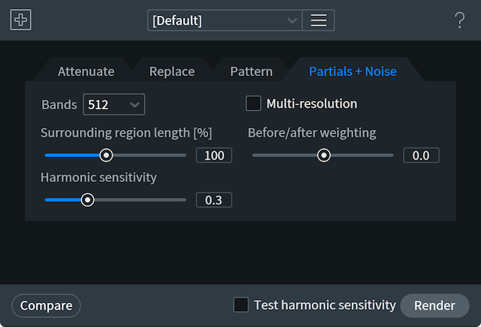
- BANDS: Selects the number of frequency bands used for interpolation.
- A higher number of bands can provide better frequency resolution, but also requires wider surrounding area to be analyzed for interpolation.
- A lower number of bands is ideal for processing short selections or transient signals.
- A higher number of bands can provide better frequency resolution, but also requires wider surrounding area to be analyzed for interpolation.
- SURROUNDING REGION LENGTH: Defines how much of the surrounding content will be used for interpolation.
- HARMONIC SENSITIVITY: Adjusts amount of detected and linked harmonics.
- Lower values will detect fewer harmonics
- Higher values will detect more harmonics and can introduce some unnatural pitch modulations in the interpolated result.
- Lower values will detect fewer harmonics
- MULTI-RESOLUTION: The multi-resolution mode allows for better frequency resolution for the interpolation of low-frequency content and better time resolution for the interpolation of high-frequency content.
- BEFORE/AFTER WEIGHTING: Gives more weight to the surrounding audio before or after the selection.
Surrounding Region Display
- SURROUNDING REGION SHADING: When using the Spectral Repair module, your selections will be shown with a dotted line surrounding your selected region. This dotted line is directly controlled by the Surrounding Region and Before/After Weighting controls inside of your Spectral Repair modules, and provides a visual representation of your set values.
- The surrounding region is the region that RX uses for interpolation of the selected region. The data from the surrounding region is used to restore the selected region.
- The surrounding region is the region that RX uses for interpolation of the selected region. The data from the surrounding region is used to restore the selected region.
Workflow
Applying Spectral Repair
- To start working with Spectral Repair, switch to the spectrogram view by dragging the spectrogram/waveform transparency balance slider to the right.
- Next, identify the unwanted event on a spectrogram and select it using a selection tool (use the time-frequency, brush, lasso or magic wand tools to fit your selection to the corrupted audio)
- You can audition just the signal in your selection by pressing the Play Selection button in the RX transport.
- Once you’ve found the event(s) to repair, select the appropriate Spectral Repair mode from the tabs at the top of the Spectral Repair settings window.
- You can use the Compare Settings functionality to audition the processing before applying it, or click the process to apply the active Spectral Repair tab’s settings.
More Information
This section contains useful information, examples and tips for getting the most out of the Spectral Repair module.
Visual Example
The following image shows the selection before processing on the top and the selection after processing with Spectral Repair on the bottom.
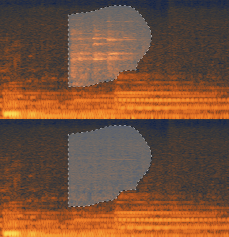
Processing Limitations
Depending on the mode and settings, Spectral Repair will have varying limits to the amount of audio that can be processed in your selection.
- Unlimited — Attenuate when in Vertical mode only.
- 10 seconds — Attenuate Horizontal or 2D; Replace modes.
- 4 seconds — Pattern, Partials + Noise modes.
- Longer selections will automatically adjust processing to use the correct mode.
Spectral Repair as an alternative to De-click processing
When used with a time selection, Spectral Repair is able to provide higher quality processing than De-click for long corrupted segments of audio (above 10 ms).
Example use cases for Spectral Repair
When used with a time/frequency, lasso, brush, or wand selection, it can be used to remove (or attenuate) unwanted sounds from recordings, such as: squeaky chairs, coughs, wheezes, burps, whistles, dropped objects, mic stand bumps, clattering dishes, mobile phones ringing, metronomes, click tracks, door slams, sniffles, laughter, background chitchat, digital artifacts from bad hardware, dropouts from broken audio cables, rustle sounds from microphone movements, fret and string noise from guitars, ringing tones from rooms or drum kits, squeaky wheels, dog barks, jingling change, or just about anything else you could imagine.
Spectral Repair can also effectively repair gaps or replace audio intelligently by using advanced resynthesis techniques.
Increase efficiency with the Find Similar Event Tool
Some unwanted events consist of several separate regions on a spectrogram.
In some cases, it’s possible to achieve more accurate results by repairing several smaller selections one by one, instead of one large selection.
You can use the Find Similar Event tool to save time when searching for and fixing many similar events in large files.
Use the Compare Settings window to experiment with Spectral Repair processing
Sometimes it’s worth trying several different methods or number of bands to achieve the desired result. A higher number of bands doesn’t necessarily mean higher quality! We encourage you to use the Compare Settings window to experiment and find the best settings for the project at hand.
Adjust Surrounding Region Length and Before/after weighting to perfect your processing
Common parameters for many modes include Surrounding region length which determines how far around the selection Spectral Repair will look for a good signal. Before/after weighting allows you to use more information from either before or after the selection for interpolation. For example, if your unwanted event is just before a transient (such as a drum hit) in the audio, you may want to set this parameter to use more of the audio before the selection to prevent smearing of the transient into the selection.
Voice De-noise
| Module & Plug-in |
|---|
Overview
Voice De-noise is an intuitive, zero latency de-noiser that offers high quality results on a variety of material.
Voice De-noise can intelligently analyze speech signals and determine the best noise threshold for your signal. In a DAW, this feature can be used to write automation in case you need to override the automatic settings and correct the noise threshold by hand.
How does Voice De-noise processing work?
- Under the hood is a series of 64 psychoacoustically spaced bandpass filters which act as a multiband gate to pass or stop a signal based on user-defined threshold values.
- If a signal component is above the threshold for the filter, it will be passed (not processed).
- If a signal component is below the threshold for the filter, it will be attenuated (processed).
Controls
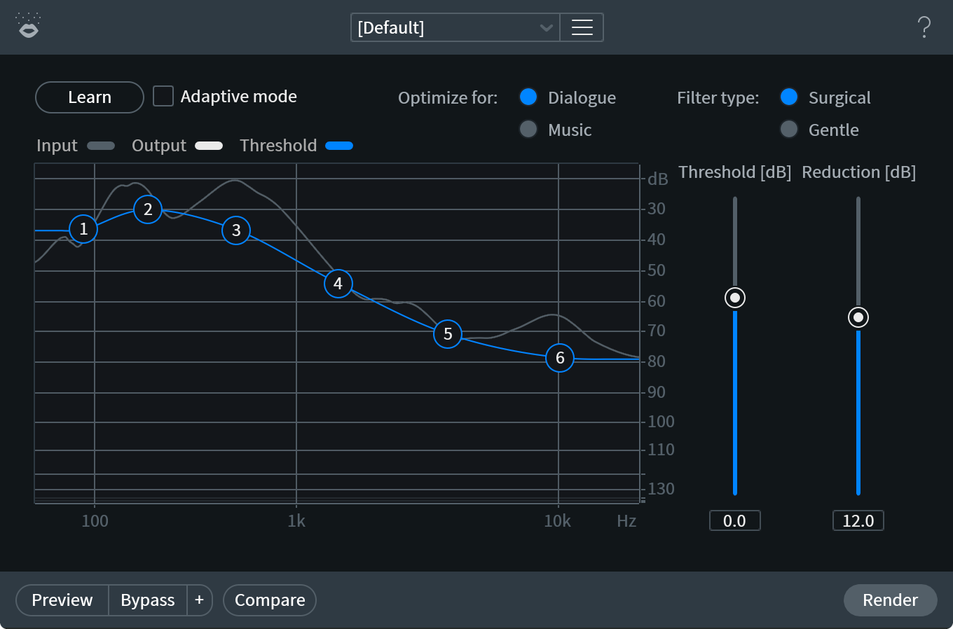
ADAPTIVE MODE: Analyzes the incoming signal and adjust the noise threshold automatically to compensate for changes in the noise floor. This can be useful for removing noise from recordings with variable noise floor and continual noisy sections, and works well for almost any recording of dialogue and spoken word.
Adaptive mode considerations
- The noise threshold settings in Adaptive Mode may be different from the settings achieved by running Learn to set the noise threshold manually.
- Because the adaptive noise threshold is continually being adjusted, it is set lower to prevent artifacts from occurring.
- The noise threshold settings in Adaptive Mode may be different from the settings achieved by running Learn to set the noise threshold manually.
LEARN: When using Manual mode, you can use the Learn button to set the noise threshold to a noise reference.
Tips for Learning a noise profile
- Find a passage of pure noise in your audio and use Learn to analyze it.
- Longer selections of noise will set the Threshold Nodes to more ideal locations.
- We recommend finding at least one second of pure noise to Learn your noise profile from.
- Find a passage of pure noise in your audio and use Learn to analyze it.
OPTIMIZE FOR DIALOGUE OR MUSIC: Because dialogue tends to be in short bursts and vocals tend to have sustained notes, we’ve added modes to provide better results when applying Voice De-noise processing.
- Optimize for DIALOGUE reacts to noise changes faster and isn’t meant to handle the noise found in sung vocals.
- Optimize for MUSIC does not attenuate sustained notes and is more transparent when applied to sung vocals.
- Optimize for DIALOGUE reacts to noise changes faster and isn’t meant to handle the noise found in sung vocals.
FILTER TYPE: Choosing the filter type changes the bandwidth of the noise reduction filters.
- SURGICAL Mode: Removes more unwanted noise than Gentle Mode, but makes some sacrifices in terms of timbre and can lead to musical noise artifacts.
What is musical noise?
- Musical noise is caused by random statistical variations of noise spectrum that cause random triggering of sub-band gates. These artifacts are sometimes described as “chirpy” or “watery” sounds left behind during the noise reduction process.
- Musical noise is caused by random statistical variations of noise spectrum that cause random triggering of sub-band gates. These artifacts are sometimes described as “chirpy” or “watery” sounds left behind during the noise reduction process.
- GENTLE Mode: provides more transparent noise reduction than Surgical, but removes less high end “sizzle.”
- SURGICAL Mode: Removes more unwanted noise than Gentle Mode, but makes some sacrifices in terms of timbre and can lead to musical noise artifacts.
THRESHOLD NODES: The Threshold Node controls on the frequency spectrum display allow you to modify the noise threshold curve, which can be thought of as the “noise profile.” These six points can be adjusted manually to suit the noise currently in your signal. These controls can be automated to compensate for shifts in the audio’s noise floor.
- In ADAPTIVE Mode, the Threshold Nodes are adjusted automatically in real-time.
- In MANUAL mode, more than one Threshold Node can be selected at a time for manual adjustment by clicking and dragging anywhere on the interface.
- In ADAPTIVE Mode, the Threshold Nodes are adjusted automatically in real-time.
THRESHOLD: The master Threshold control allows you to offset all Threshold Node values by the same amount. If you find that processing is too aggressive or processing is affecting audio you want to leave unprocessed, try adjusting this control.
REDUCTION: Provides control over the maximal depth of noise reduction (in dB) that will occur per frequency band while a signal component is below its threshold. If you have your thresholds set properly and don’t like the results you’re getting, try adjusting this control.
METERING
- The Input Spectrum meter shows the level of the signal at the input of the denoiser filters.
- The Output Spectrum meter shows the level of the signal at the output of the denoiser filters.
- The Gain Reduction Region is the area between the Input and Output Spectra. This shows the amount of noise reduction processing being applied to your signal.
- The Input Spectrum meter shows the level of the signal at the input of the denoiser filters.
Voice De-noise Plug-in
Voice De-noise has been specifically designed to provide high efficiency, zero latency adaptive noise removal when inserted on a track in your DAW or NLE. The Spectral De-noise plug-in is far more resource intensive and uses higher latency.
Azimuth [ADV]
Overview
The Azimuth module provides control over left and right channel gain and delay. Azimuth adjustment can help repair stereo imbalances and phase issues that can occur as a result of issues introduced by speed inconsistencies.
Controls
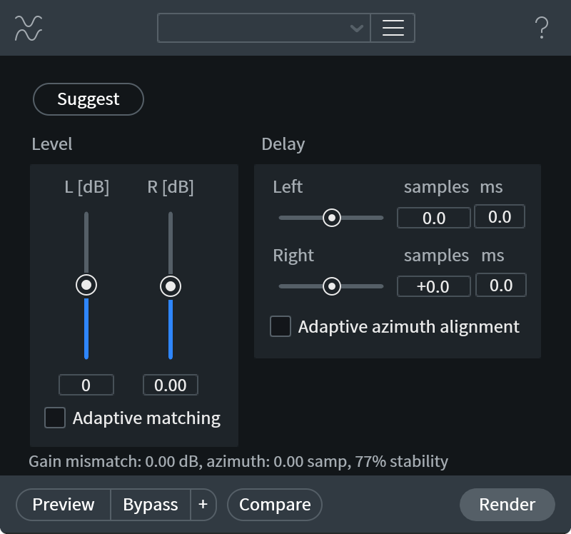
- LEVEL (dB): Adjusts the gain of the left and right audio channels
- ADAPTIVE MATCHING: Enables automatic gain adjustment of the right channel in order to match the level of the left channel over time.
- DELAY (samples/ms): Allows for manual adjustment over the delay in samples or milliseconds of the left and right audio channels. For very accurate azimuth correction, RX uses oversampling to achieve sub-sample delays.
- ADAPTIVE AZIMUTH ALIGNMENT: Enables automatic time-variable adjustment of the right channel’s sample delay in order to align the waveform with the left channel.
- SUGGEST: Analyzes the selection and determines the appropriate amounts of fixed gain and delay to apply in order to align the two channels.
Suggest & Adaptive modes are only available on stereo files
The Suggest function and Adaptive Matching modes are meant to function on stereo files, these controls will be disabled in the Azimuth module interface when a mono file is selected.
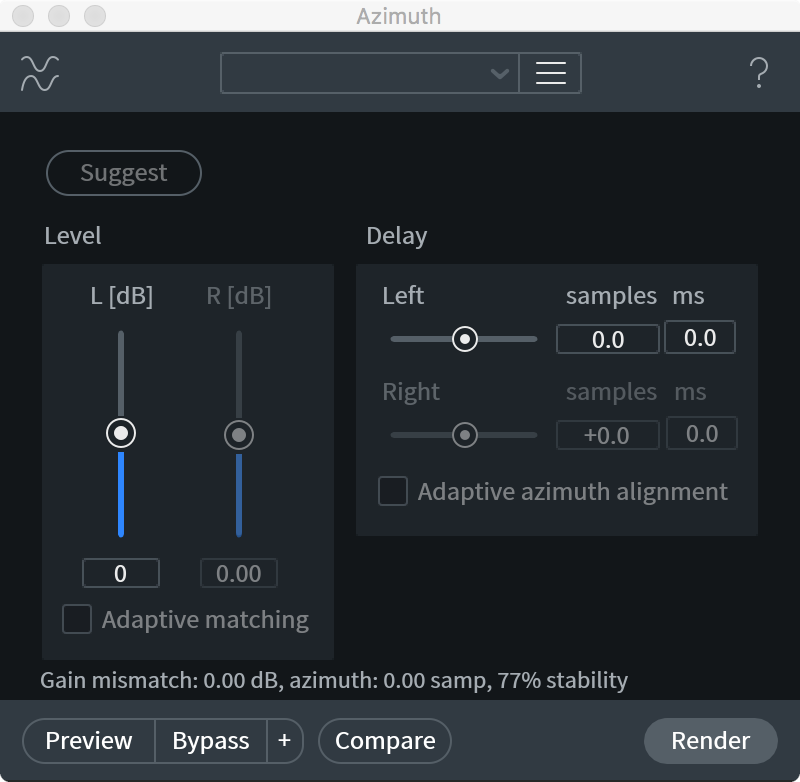
More Information
Use Azimuth to fix gain and delay alignment issues
Azimuth adjustment can be useful to repair inconsistent gain or delay alignment between left and right channels.
For example, gain and delay alignment inconsistencies can be introduced by improper tape head alignment.
Use Azimuth before processing with Center Extract
Azimuth adjustment is recommended to be applied before Center Extract processing to achieve the best results.
Dither [STD & ADV]
Overview
Dithering is a necessary process when converting audio from a higher bit resolution to a lower bit resolution.
Dithering is used to tame the quantization distortion that happens when converting between bit depths due to requantization. Dither also preserves more of the dynamic range of a signal when converting to a lower bit depth.
The Dither module applies iZotope’s MBIT+ dithering and noise shaping technology to maintain the highest audio quality possible when you are converting to 24, 20, 16, 12, or 8 bits.
MBIT+ uses psychoacoustic methods to distribute dithering noise into less audible ranges. The result is a more pleasing sound and smoother fades.
Controls
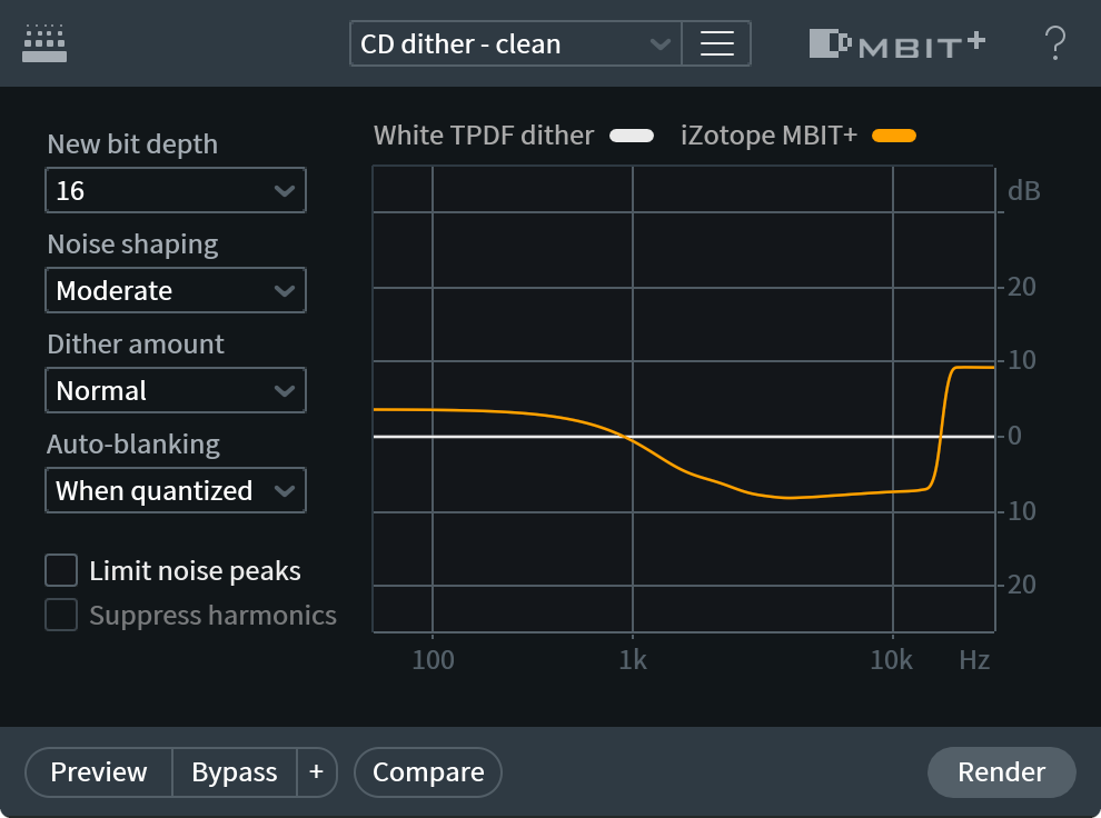
New Bit Depth
This sets the target resolution (bit depth) of the audio file.
Noise Shaping
Sets the aggressiveness of dither noise shaping.
It is possible to provide more effective and transparent dithering by shaping the dithered noise spectrum so less noise is in the audible range and more noise is in the inaudible range.
You can control the aggressiveness of this shaping, ranging from None (no shaping, plain dither) through Ultra (roughly 14 dB of audible noise suppression).
More noise shaping can cause slightly higher peaks in your signal, even at high bit depths.
Dither Amount
The dithering amount can be varied from None (noise shaping only) to High.
- In general, the Normal dither amount is a good choice.
- No dithering or Low dither amount can leave some non-linear quantization distortion or dither noise modulation, while higher settings completely eliminate the non-linear distortion at the expense of a slightly increased noise floor.
- A dither amount setting of High with no noise shaping produces a standard TPDF dither: a common white noise generation method with a triangular distribution of amplitudes between −1 and +1 of the Least Significant Bit (LSB).
Auto-blanking
Automatically mutes dither output (i.e. dither noise) based on the selected mode and characteristics of the input signal. Auto-blanking mode options include:
- IF QUANTIZED: Mutes dither output when already dithered or quantized signal is detected. When existing quantization is detected, the auto-blanking feature will mute dither until a signal with no existing dither is detected.
- ON SILENCE: Mutes dither output when silence is detected.
- OFF: Disables auto-blanking.
Limit Noise Peaks
Dither noise is random in nature and has a very low amplitude. However, after noise shaping, especially in aggressive dithering modes like Ultra, the high-frequency dither noise is significantly amplified, and the overall dither signal can show spurious peaks up to −60 dBFS during 16-bit quantization. If such high peaks are undesirable, you can enable this option to effectively suppress the spurious peaks in the noise-shaped dither.
Suppress harmonics
If, for some reason, any dithering noise is undesirable, simple truncation remains the only choice. Truncation results in harmonic quantization distortion that adds overtones to the signal and distorts the timbre. In this case you can enable Suppress Harmonics option to slightly alter the truncation rules, moving the harmonic quantization distortion away from overtones of audible frequencies. This option doesn’t create any random dithering noise floor. Instead it works more like truncation, but with better tonal quality in the resulting signal. This option is applicable only in the modes without dithering noise and without aggressive noise shaping.
EQ [STD & ADV]
Overview
RX includes an eight-band parametric EQ module with six adjustable notch/shelving filters and two adjustable passband filters. The EQ module is useful for manually shaping the overall sound of a file or selection, for both corrective and enhancement purposes. Beyond a traditional equalizer, the EQ also offers remarkably high Q values for precision filtering.
EQ can often be a simple first step to preparing a file for restoration, and can be used for cutting harsh high frequencies, removing rumble from dialogue, steeply high passing out wind noise from a location recording, or cutting distortion overtones to increase the intelligibility of a voice.
Controls
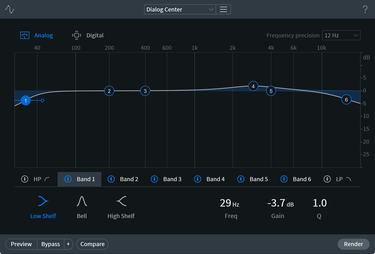
EQ TYPE
- Analog (IIR): a minimum-phase EQ with analog-like EQ curves.
- Digital Linear Phase (FIR): a linear-phase EQ with surgical EQ curves.
FREQUENCY PRECISION
This controls the number of bands, i.e. frequency resolution vs. time resolution, for the FIR filter. A lower value will increase the frequency resolution, for tighter cuts, at the expense of potentially introducing filter ringing.
FREQUENCY & GAIN
You can adjust an EQ band by clicking on a node and dragging it to change the frequency and gain of the band.
- You can click and drag to select multiple filter nodes and move them as a group.
Q/BANDWIDTH
If you move the mouse over the bracket handles on the side of the band, you can adjust the Q or bandwidth of the EQ by dragging with the mouse. You can also adjust Q of the selected filter with the mouse wheel.
More Information
Interacting with the EQ nodes
To adjust the EQ curves, grab an EQ node and drag it to a new point on the grid. When a node is selected, handles on either side of it appear which can be dragged together or apart to control the bandwidth of the node. Alternately, you can enter precise EQ settings by typing values into the table below the main EQ grid.
Choosing between Analog and Digital EQ Types
There are reasons why you may want to use one EQ mode over another. Analog mode uses shapes based on analog equalizers, implemented as digital IIR filters. One reason to use this mode is that analog bells are narrower than our digital shapes at high Q values. Since these shapes are minimum-phase, they cause no pre-echos. Also, since they match analog designs, they can be used to emulate what an analog equalizer would do, or reduce damage caused by an analog equalizer.
Digital mode uses special shapes designed to correct audio problems as surgically as possible, implemented as FIR filters. These shapes, unlike the Analog shapes, affect only precisely defined frequency ranges. In Digital mode the EQ is linear-phase, meaning no phase shift will occur.
EQ curve display & EQ Type
You may notice a slight difference in the visual shape of the bell filter when moving between Analog and Digital modes. Analog mode follows the traditional shapes of analog circuitry, while Digital mode uses special filters designed by iZotope. While these shapes are similar between the two modes, they will not be identical.
Composite EQ Curve Display
As you adjust a band you will see two EQ curves. The white curve is the composite of all EQ bands while the curves colored the same shade as the node shows the EQ curve of the selected band.
EQ Match [ADV]
Overview
The EQ Match module lets you match the EQ profile of a selection with the profile of a different selection. This is useful if you’re ever tasked with matching a lav mic with a boom mic, matching location dialogue to ADR or vice versa, or perhaps you had multiple mics on an audio source that you’d like more closely aligned in terms of frequency response.
Controls
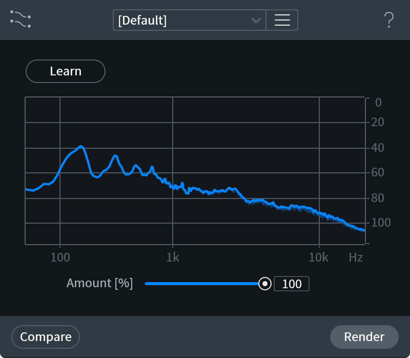
AMOUNT
Sets how closely the frequency spectrum you’re processing will be matched to the learned spectrum. Many times, using a 100% match could sound unnatural, and lower values, between 10-40% do enough to make the two audio signals more closely aligned.
Workflow
How to Apply EQ Match to different selections
- Open the EQ Match module
- Make a selection in a file.
- Click Learn.
- Make another selection.
- Click Process.
How to save a captured spectrum as an EQ Match Preset
- In EQ Match, click the preset menu to the right of the preset drop-down menu.
- Select Add Preset.
- Enter the name for the new preset.
- Press Enter.
Fade
Overview
The Fade module can be used to apply a gradual increase or decrease to gain throughout your selection. Different amplitude curve options are available in the Fade Type menu. For in-phase tonal material, a Cosine fade curve will work well, while the Equal power fade type can be more effective on noisy material.
Controls
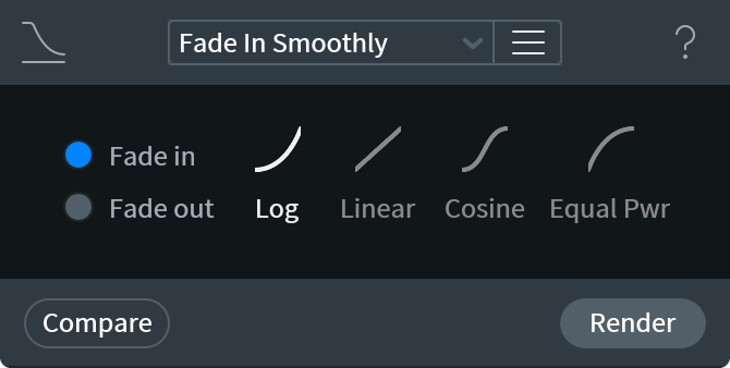
Fade Type
- Log: Logarithmic fade for general use
- Linear: Linear fade for general use
- Cosine: Cosine fade for crossfades of in-phase tonal audio material
- Equal power: Equal power fade for crossfades of noisy audio material
Instant Process Tool
[STD & ADV]
Fade is available as an option in the Instant Process menu. When Fade is selected and Instant Process is enabled, the active settings in the Fade module will be applied to your selection. For example: if the Fade module is set to Fade in: Log (as shown in the image above) the Fade in: Log type of fade will be applied every time you use the Instant Process Tool in ‘Fade’ mode.
Find Similar
Overview
There are times when you may have many similar audio events to manually repair. In cases like this, manually selecting and processing each event can be time consuming. RX includes a Find Similar Event tool which takes your selection and finds all related instances of that audio event. You can choose from Find Next, Find Previous, and Find All.
Controls
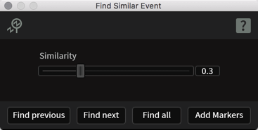
SIMILARITY
Lower values will find more events. The higher the value, the more similar an event must be to the original event selection for it to be detected.
FIND PREVIOUS
Searches before the current selection for a similar event.
FIND NEXT
Searches after the current selection for a similar event.
FIND ALL
Searches the entire file for events similar to the current selection.
Gain
Overview
The gain module is useful for bringing the level of your audio up or down. Gain can also be applied to a specific time-frequency selection, allowing you to manually attenuate or boost selections in the Spectrogram window.
Controls
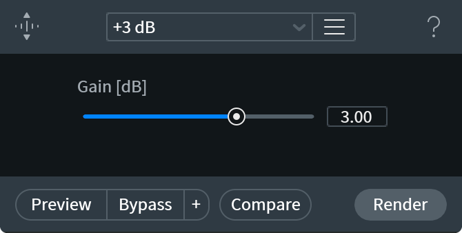
GAIN
Boosts or cuts the level of the signal by the designated decibel amount.
Instant Process Tool
[STD & ADV]
Gain is available as an option in the Instant Process menu. When Gain is selected and Instant Process is enabled, the active settings in the Gain module will be applied to your selection.
Leveler [ADV]
Overview
The Leveler module automatically rides the gain in your file to even out the variations of the signal level. The algorithm consists of a compressor with a makeup gain to achieve a smooth signal that’s aiming towards (though may not exactly hit) a desired Target RMS level. The compressor has the ability to prevent pumping on speech pauses or breathing sounds, using the Optimization mode, for either Dialogue or Music, in addition to the Ess and Breath parameters.
The level detector stage includes the K-weighting filter that helps equalize the audible loudness, not just RMS level. However, the Leveler module is designed for the smoothing of overall audio signals, rather than taking an entire signal and using a fixed gain to ensure it hits a loudness compliant LKFS level, which is the goal of the Loudness module.
This all combines to create a transparent, non-destructive Clip Gain curve, without the color or artifacts of a traditional compressor.
Unlike the Loudness module, which applies a constant gain based on Loudness compliant analysis to the whole file, Leveler applies a time-variable gain. For convenience of RX users, the time-variable gain is applied as a Clip Gain envelope, which can be viewed and edited by the user.
Please Note
- If additional processing is applied from another module after running Leveler, the clip gain values assigned by Leveler will be destructively written to the file and the clip gain nodes will return to zero. However, the clip gain settings from Leveler will be saved in the Undo History list).
Controls
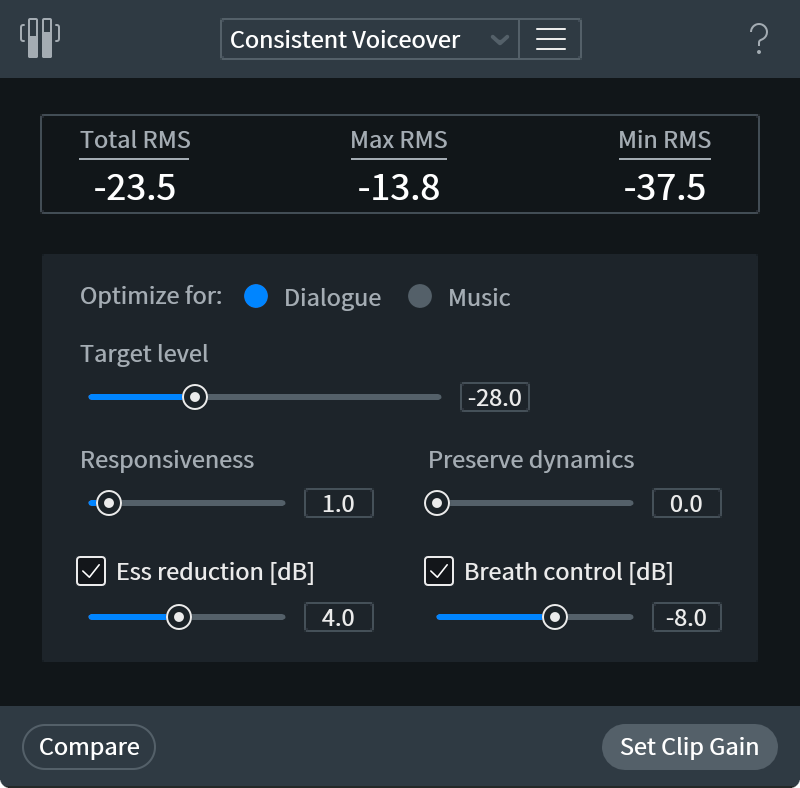
NUMERICAL READOUTS
Numerical Readouts provide you with the Total, Maximum and Minimum readouts for RMS.
- The total value is the overall RMS of your audio signal, which may inform where you choose to set the Target RMS level parameter.
OPTIMIZE FOR
Optimize For switches between two modes, Dialogue and Music. Each mode utilizes a slightly different handling of the noise floor.
- Dialogue tends to be audibly juxtaposed against the noise floor, as it’s typically very transient, whereas music often tends to fade into the noise floor, with chords, notes, and other instrumental decays.
- Switching between these two modes will affect the behavior of the Leveler, and prevent pumping.
TARGET LEVEL
Target Level sets the desired average RMS level of the recording.
- Note that Leveler uses K-weighted RMS to better level perceived loudness, but that it is not a loudness compliant leveling tool. It uses the Target Level as a guide, but with the goal of smoothing out variations in an audio signal much more transparently than a compressor typically would. As such, it is not unusual to see the resulting output of Leveler not be an exact 1:1 with the defined Target Level.
- At high target levels, the leveler may not be able to hit the target without clipping, so the target level will not be reached.
RESPONSIVENESS
Sets the integration time for RMS level detection and is similar to the attack/release setting on a compressor.
- Lower settings will result in more aggressive Leveling, useful if a signal has a lot of sudden variations.
- Higher settings will result in smoother behavior, leveling words or phrases rather than individual syllables.
- If you find the Leveler is responding to any sudden unwanted sounds, such as a cough, and boosting it, increase the slider to a higher value to see if this results in less aggressive jumps.
PRESERVE DYNAMICS
This can be thought of the maximal amount of gain applied by the Leveler. The wider the range of gain adjustments allowed, the further away from the original dynamic range the audio signal will be.
- At lower values, the Leveler will preserve fewer of the original dynamics in the audio signal.
- At higher values, the Leveler will preserve more of the original dynamics in the audio signal.
ESS REDUCTION
Ess Reduction is aimed at anyone using the Leveler on dialogue or vocals, and utilizes a smart algorithm, inspired by the DBX 902 De-esser, to detect when ess is present in a signal, and then attenuate it accordingly. This avoids adding any boost to esses, which may otherwise be seen as quiet sounds requiring a boost. The slider sets the amount of ess reduction, applied in dB.
BREATH CONTROL
Breath Control will automatically detect breaths in your vocal takes and attenuate them. This saves time when editing dialogue or vocal tracks, and streamlines a task that is typically done manually.
- Breath Control automatically analyzes the incoming audio and distinguishes breaths based on their harmonic structure. If any piece of the incoming audio matches a harmonic profile similar to a breath, the Leveler will apply a Clip Gain adjustment.
- Different from a ‘Threshold’ based process in which the module is only engaged once the audio has risen to a certain volume, this feature will perform its analysis regardless of level.
- This allows for accurate breath recognition with a multitude of quiet or loud dialogue / vocal styles with minimal adjustment of the module’s controls.
- The slider represents the desired level, in dB, that you wish all detected breaths to be reduced to. This can result in much more natural sounding breath reduction as the detected breaths in your audio are only reduced when necessary.
- Loud and abrasive breaths will be reduced heavily, and quiet, natural sounding breaths will be left at the same volume. The volume level specified by this slider is a guide, but may not result in exact values.
LIMITER
The Leveler has a built-in Limiter in order to avoid introducing any clipping to the audio signal once the Clip Gain envelope has been applied.
- This cannot be adjusted, but you’ll see the Clip Gain envelope smooth off an audio signal if you’re pushing peaks close to 0 dB.
Loudness [ADV]
Overview
The Loudness module adjusts the gain of the signal in order to meet the specified loudness standard, such as BS.1770. Unlike the Leveler module, the gain in Loudness module stays fixed in time. However a post-limiter will be applied to the signal, if it is required to meet the True peak specification.
Controls
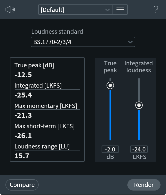
Loudness standard
Specifies the loudness standard used for calculating loudness and sets Integrated loudness and True peak sliders to the target values typical for the standard. See the Loudness Standard chart below for more information about the different loudness standards.
Integrated loudness
Sets the desired integrated loudness of the clip, in LKFS (which is the same as LUFS).
True peak
Sets the maximum true peak value allowed in a clip.
Integrated loudness & True peak level Compatibility Note
- Note that some combinations of Integrated loudness and True peak level may be incompatible.
- For example, having loudness of −10 LKFS is not compatible with a true peak value of −20 dBTP.
- When settings are incompatible, the Loudness module will display a warning at the end of the processing pass.
Workflow
To use the Loudness module:
- Make a selection in your file. If you want to apply Loudness to the entire clip, click Edit > Select All or Edit > Deselect All.
- Click Process > Loudness.
- Select a preset, or make adjustments to the Integrated loudness and/or True peak sliders.
- Click Process.
Loudness Standards
| Loudness Standard | Integrated | Integrated Tolerance (+/-) | Short-term | Momentary | True Peak | Gating |
|---|---|---|---|---|---|---|
| AGCOM 219/09/CSP | -24 | 0.5 | Off | Off | -2 | On |
| ARIB TR-B32 | -24 | 2 | Off | Off | -1 | On |
| ATSC A/85 | -24 | 2 | Off | Off | -2 | On |
| BS.1770-1 | -24 | 2 | Off | Off | -2 | Off |
| BS.1770-2/3/4 | -24 | 2 | Off | Off | -2 | On |
| EBU R128 | -23 | 0.5 | Off | Off | -1 | On |
| OP-59 | -24 | 1 | Off | Off | -2 | On |
Mixing
Overview
Provides specific control over both left and right signal and balance levels. This simple operation can be used to downmix stereo material into mono, invert waveforms, transcode left/right stereo into mid/side, subtract a center channel, and much more.
Controls
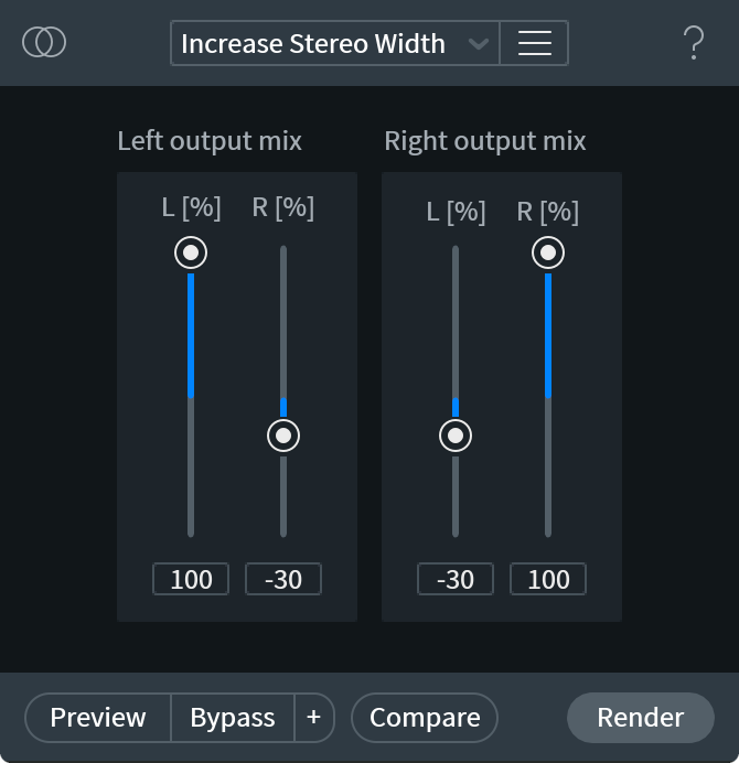
Left Output Mix (%)
Allows you to define how much of the current selection’s left and right channel signal will be present in the new target left channel.
Right Output Mix (%)
Allows you to define how much of the current selection’s left and right signal will be present in the new target right channel.
Normalize
Overview
The Normalize module applies enough gain to set the sample peak level of your signal to the specified Target Peak Level.
Controls
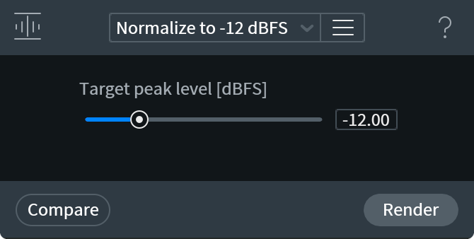
- Target Peak Level [dBFS]: Determines the maximum peak level of a signal as a result of normalization.
Phase
Overview
The Phase module balances asymmetric waveforms by rotating signal phase. Rotating the phase of a signal changes its peak values but doesn’t change its loudness, and otherwise has no audible effect on the signal.
Controls

Adaptive Phase Rotation
Continuously analyzes the audio selection and applies the time-variable phase rotation to both left and right channels, resulting in a symmetrical waveform with minimal signal peak levels.
Adaptive phase rotation is best used on vocal material, as it can occasionally yield pitch artifacts on musical material.
Rotation (deg)
Rotates the channel’s phase by the specified degree.
When a waveform’s phase is rotated, every frequency is rotated equally. Rotating phase by 180 degrees inverts the waveform.
Suggest
Analyzes the selection for the ideal channel-linked fixed phase for reducing overall peak levels of the signal.
More Information
Asymmetric waveforms can occasionally occur in audio such as dialogue, voice, and brass instruments.
- Making the waveform more symmetrical gives the signal more headroom.
- Rotating the phase of a waveform, will change its amplitude characteristics. Phase rotation does not result in a time shift.
- Because the range of rotation is from −180 to +180 degrees, the Phase tool can be used for simpler purposes, such as inverting signal polarity.
Visual Example of Phase Rotation
The top waveform in the folloiwing image is a trumpet signal with higher peak values on one side of its waveform (meaning the waveform is asymmetrical.)
The bottom waveform in the folloiwing image has been processed by the Phase module. The processig rotated the phase of the waveform by −72 degrees to distribute its peak samples more evenly (making the waveform more symmetrical.)
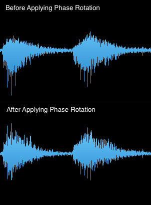
Plug-in Hosting
Overview
On Mac, the RX Audio Editor supports the use of VST2 and AudioUnit (AU) plug-ins. On Windows, the RX Audio Editor supports the use of VST2 and DirectX plug-ins. To enable the use of plug-in hosting, choose the Plug-in module from the Module List.
Using 32-bit plug-ins in the RX Audio Editor
To use 32-bit AU, VST2 or DirectX plug-ins in the RX Audio Editor, you must run the 32-bit application.
- On Windows, open the “RX 7 Audio Editor” application from the Start menu or by double-clicking on the Desktop shortcut. Not the “RX 7 Audio Editor (64-bit)” application.
- On Mac, navigate to your Applications folder and find iZotope RX 7 Audio Editor. Right-click on the the application and select “Get Info” and check the “Open in 32-bit mode” option.
- Note: When used as a VST in RX, iZotope Insight’s loudness history does not run during offline processing. You will not see metering details, unless you are using Preview.
Selection Based Processing
With a plug-in loaded in the Plug-in module, you can make use of the same audio selection tools and Preview and Compare options that are available for other RX modules.
This can allow for very detailed processing and greater accuracy when working with your existing plug-ins, giving you audio selection options unavailable in a traditional DAW setup.
Plug-in Presets
Only one plug-in may be loaded at a time. However, with the use of presets, multiple settings and presets may be recalled quickly in order to move between plug-in instances.
When your plug-in is configured the way you would like it, select Add Preset from the small Preset drop down arrow.
Assign Presets to Keyboard Shortcuts
Once your preset is named and saved, you can then assign that plug-in and preset to a keyboard shortcut with the Set Preset Shortcut feature.
This keyboard shortcut will recall not only the plug-in settings, but the plug-in instance itself. As such, if a preset is saved with Plug-in 1, and Plug-in 2 is currently loaded into RX’s plug-in window, pressing the preset keyboard shortcut will re-instantiate Plug-in 1 and recall the exact settings when the preset was made.
This can allow for very quick editing, processing, and recall of plug-in instances and settings, providing a quicker workflow than traditional DAW track/mixer environments.
Resample [STD & ADV]
Overview
The Resample module allows you to convert an audio file from one sampling rate to another.
Sample Rate Conversion (SRC) is a necessary process when converting material from one sampling rate (such as studio-quality 96 kHz or 192 kHz) to another rate (such as 44.1 kHz for CD or 48 kHz for video).
It is common to record and edit in high sampling rates since higher rates allow higher frequencies to be represented. For example, a 192 kHz audio sample can represent frequencies up to 96 kHz whereas a 44.1 kHz audio sample can only represent frequencies up to 22.05 kHz. The highest frequency that can be represented accurately by a sampling rate is half of the sampling rate, and is known as the Nyquist frequency.
When reducing the sampling rate, or downsampling, it is crucial to remove the frequencies that cannot be represented at the lower sampling rate. Leaving frequencies above this point causes aliasing. Aliasing can be heard as the frequencies in an inaudible range are shifted into an audible range, causing distortion and noise. With iZotope SRC’s steep low-pass filter, users can completely avoid the common aliasing artifacts while maintaining the maximum frequency content.
Link: Comparison of iZotope's SRC process
- A comparison of iZotope’s SRC process versus other sample rate convertors can be viewed at: http://src.infinitewave.ca/
Controls
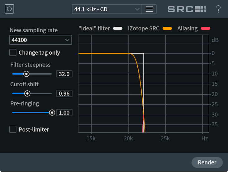
Note about the red aliasing curve display
- The Aliasing portion of the curve displayed in red shows the reflected frequencies during downsampling or imaged frequencies during upsampling — both due to aliasing.
New sampling rate
This setting chooses the sampling rate you want to convert to. Choose a sampling rate from the drop-down list, or click on the field to type in a custom sampling rate.
Change tag only
Changes the declared sampling rate of the file in the file’s properties without resampling the file, effectively changing the playback rate and pitch of the file.
When to use Change Tag Only option
- This feature is useful if the sampling rate tag was damaged by a previous audio editing process and the file is playing back incorrectly.
Filter steepness
This allows you to control the steepness of the SRC filter cutoff. The white line is representative of an ideal low-pass filter.
Note about higher filter steepness values
- Higher filter steepness means better frequency performance of the filter: wider passband retains more useful signal, while stronger stopband attenuation provides better rejection of aliasing. At the same time, higher steepness of the frequency response requires a longer filter, which produces more ringing in time domain and energy smearing near the cutoff frequency.
Cutoff shift
SRC filter cutoff frequency shift (scaling multiplier).
Allows shifting the filter cutoff frequency up or down, to balance the width of a passband vs. amount of aliasing.
Pre-ringing
SRC filter pre-ringing amount in time domain (0 for minimum phase, 1 for linear phase, or anywhere in between).
Adjusts the phase response of the filter, which affects its time-domain ringing characteristic. The value of 0 produces a minimum-phase filter, which has no pre-ringing, but maximal post-ringing. The value of 1 produces a linear-phase filter with a symmetric impulse response: the amount of pre-ringing is equal to the amount of post-ringing. Intermediate values between 0 and 1 produce so-called intermediate-phase filters that balance pre- and post-ringing while maintaining linear-phase response across a possibly wider range of frequencies.
Post-limiter
Keeps true peak levels of the output signal below 0 dBTP to prevent any clipping from occurring.
When to use the post-limiter
- This option is important when resampling signals that are very close to 0 dB, because filtering during resampling can change peak levels of a signal.
- Engage the Post-limiter option in order to limit the output levels of your signal to prevent any clipping from occurring.
Signal Generator
Overview
The Signal Generator is able to synthesize silence, tones, and noise. This is useful for creating test tones, calibration tones for post production delivery specs, repairing DC offset, and even using it as a “bleep” module to eliminate obscenities in a dialogue edit.
The Signal Generator module is capable of generating extremely accurate test tones for research and testing purposes.
Silence
Silence generates digital silence, which can be used to adjust spacing or duration of your file.
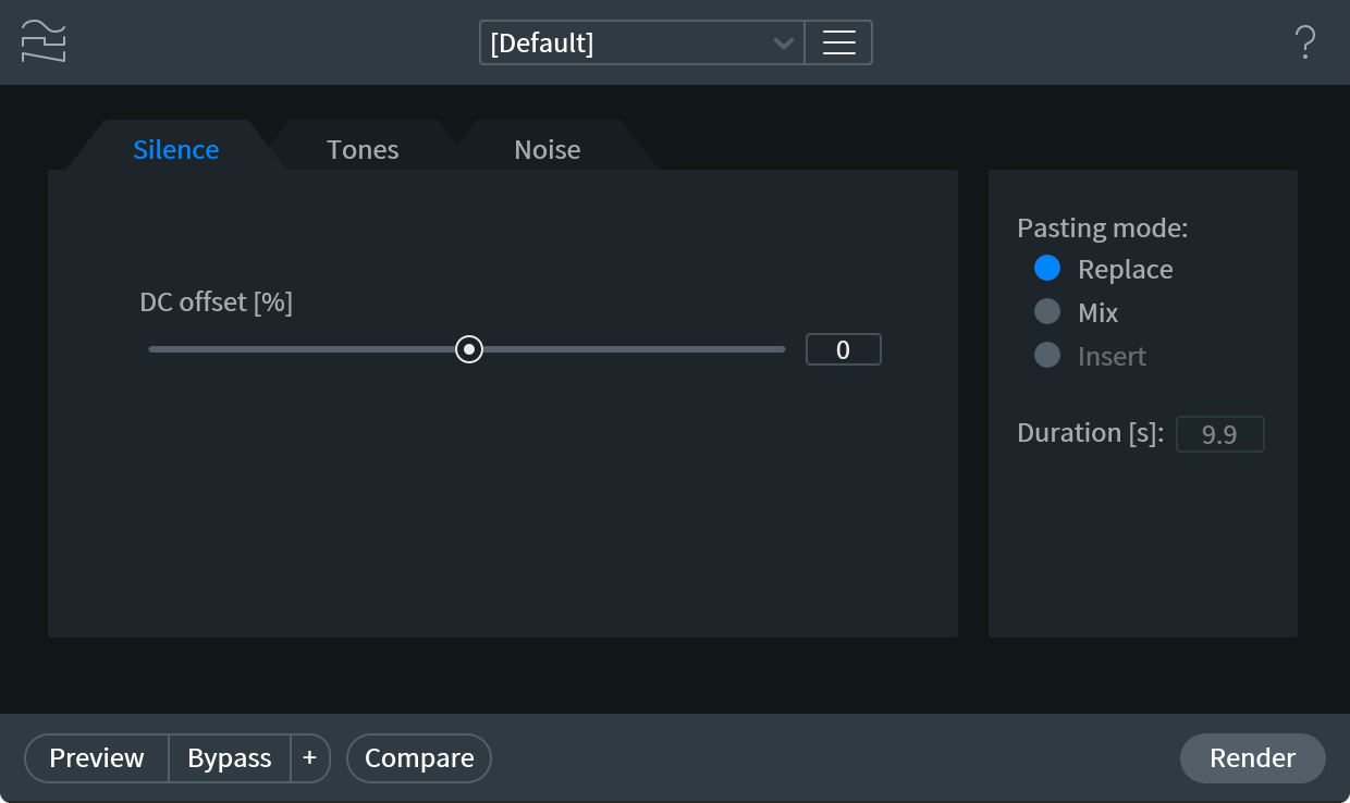
DC Offset
Creates or removes positive or negative amounts of DC offset.
Tones
The Tones tab allows you to generate signals.
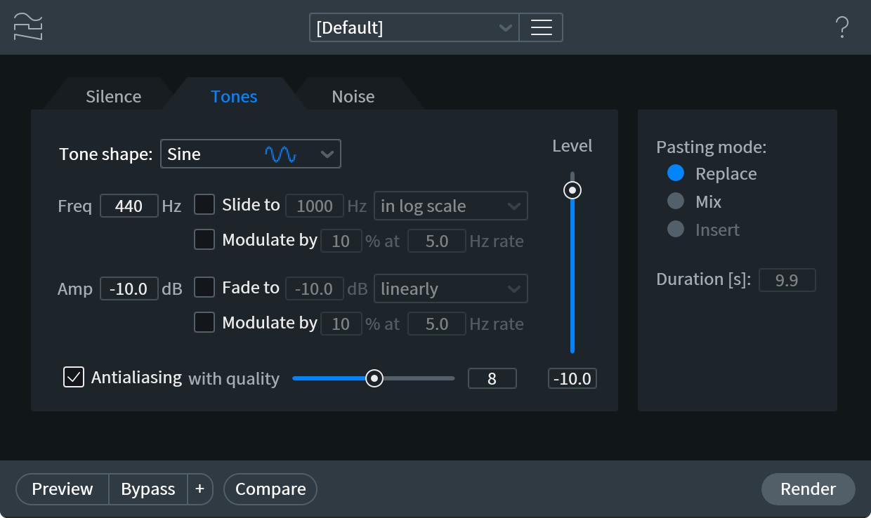
- TONE SHAPE: Tone shape allows you to choose the waveform for the signal to be generated, with a choice of:
- Sine
- Triangle
- Sawtooth
- Square
- Sine
- FREQ: Sets the frequency, in Hertz (Hz), of the signal to be generated.
- AMP: Sets the amplitude, in Decibels (dB), of the signal to be generated.
- ANTIALIASING: All test tone shapes, except the sinusoid, contain an infinite set of harmonics. When Antialiasing is not selected, these tones are generated in a “naive” way in the time domain. It leads to aliasing (folding) of higher harmonics into the audible range, which often sounds undesirable.
- When Antialiasing option is enabled, these higher harmonics are filtered out with a linear-phase low-pass filter. It prevents aliasing, but introduces some ringing into the waveform, which is usually not a problem, because it is concentrated near half the sampling rate.
- Higher quality of antialiasing produces a filter with a sharper frequency cut, which retains more of the useful harmonics and rejects more of the aliased harmonics, at the expense of more time-domain ringing and slower processing.
- When Antialiasing option is enabled, these higher harmonics are filtered out with a linear-phase low-pass filter. It prevents aliasing, but introduces some ringing into the waveform, which is usually not a problem, because it is concentrated near half the sampling rate.
- LEVEL: Specifies the sample peak level of the synthesized waveform in dBFS. When Antialiasing is used, actual sample and true peak levels may exceed the specified peak level due to filter ringing.
Noise
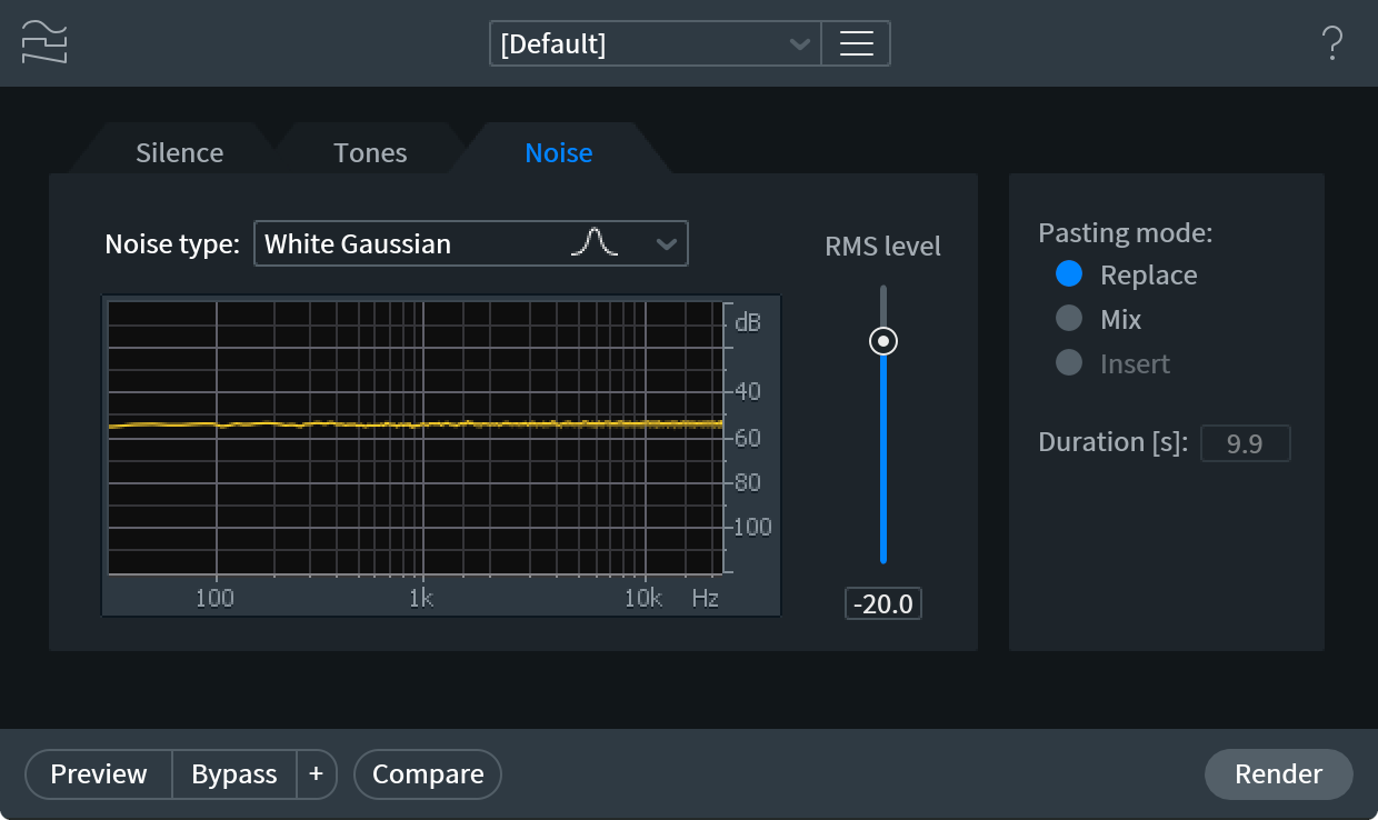
Allows you to generate noise of many different types, with a user definable RMS level. The noise types include:
- White Gaussian
- White triangular
- White uniform
- White binary
- Pink
- Brown
Noise color defines the spectral shape: white noise has flat power spectrum, pink noise decays at 3 dB/octave rate, while brown noise decays at 6 dB/octave rate.
Gaussian, triangular, uniform, or binary relates to the p.d.f., or probability distribution function, of the noise. It describes how often samples of different amplitude are encountered in the signal. For example, uniform p.d.f. means that all amplitudes below noise peak level are equally popular.
- PASTING MODE: The pasting modes affect how generated signals are added to your file.
- REPLACE: Replace will completely replace the audio in your selection with the generated signal.
- Mix: Mix will retain the audio in your selection, and mix in the generated signal.
- Insert: Insert will allow you to set a custom duration, in seconds, and the Signal Generator will then insert this audio, increasing the length of your audio file by the amount prescribed.
- REPLACE: Replace will completely replace the audio in your selection with the generated signal.
Time & Pitch [STD & ADV]
Overview
The Time & Pitch module uses the iZotope Radius™ processing algorithm to allow for independent control over the length and pitch of your audio. It is useful for retuning audio to fit in a mix better, or adjusting the length of a selection to account for changes in BPM or timecode.
Variable Pitch & Variable Time modules
- The Variable Pitch module can be used for faster pitch shifting with the ability to correct variations in pitch over time.
- The Variable Time module can be used to adjust the time stretch ratio envelope over time.
iZotope Radius
iZotope Radius™ is a world-class time-stretching and pitch-shifting algorithm. You can easily change the pitch of a single instrument, voice, or entire ensemble while preserving the timing and acoustic space of the original recording. iZotope Radius is designed to preserve the natural timbral qualities of the original file, even when applying extreme pitch shifts.
Controls
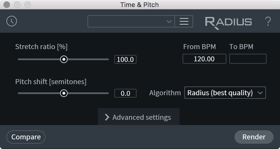
Algorithm
The Algorithm drop-down menu has three options:
Radius
Designed to work well with polyphonic material such as mixes with more than one instrument, as well as non-harmonic material such as drum loops or rhythmic audio. This is the highest-quality option for most sources.
Radius RT
Good quality, polyphonic, but faster than Radius. If processing speed is important, use the Radius RT algorithm.
Solo Instrument
Designed for monophonic pitched material such as a stringed instrument or human voice. You should use Solo mode only when processing a single instrument with a clearly defined pitch. The human voice is a good candidate for solo mode, as are most stringed instruments, brass instruments, and woodwinds.
In Solo mode, the adaptive window size can significantly affect the quality of Radius’s output.
- If the adaptive window size is too small, you will hear a squeaking noise which sounds like the pitch of the audio is changing very rapidly.
- If the adaptive window size is too large then the sound will become grainy as you will begin to hear portions of it being repeated.
- A good approach is to start with the default window size of 37 ms. If the results are unsatisfactory, increase the window size until the squeaking noise described above does not occur. If you cannot get the distortion to disappear, switch to Radius mode for processing.
- Lower pitched instruments and voices may require a longer adaptive window size than the default, but very long adaptive window sizes can cause audible repeating slices of audio.
Formant Correction
Formants are the resonant frequency components of voice that tend to be perceived as characteristics like age and gender. You can shift formants independently of pitch and time by enabling Shift Formants.
- Typically you will leave the Formant Shift Strength set to 1 (full strength) and the Formant Shift Semitones set to 0.
- If you hear what sounds like an EQ adjustment to your audio, you can try lowering the strength to reduce this artifact.
- To achieve special effects, for example to change the perceived gender of a human voice, try adjusting the semitones to a value other than 0.
STRETCH RATIO
Determines how much the resulting audio will be stretched in time.
- Values between 12.5% and 100% will cause the audio to speed up without affecting pitch, resulting in a shorter audio file.
- Values between 100% and 800% will cause the audio to slow down without affecting pitch, giving you a longer audio file.
BPM CALCULATOR
If you are using Radius to process audio for a tempo change, you can also adjust the stretch ratio with the BPM Calculator.
PITCH SHIFT
Controls the amount of pitch shifting up or down that will be applied to the audio.
TRANSIENT SENSITIVITY
Determines the algorithm’s handling of transient material. Higher values will result in better preservation of individual transients after processing.
- When stretching percussive material, you usually want transient sensitivity set to its default value of 1.
- If transients in your audio are being “smeared”, a higher value of 2 will tighten up transience at the expense of incurring heavier processing on non-transient audio.
- Bowed instruments such as the violin and cello are especially affected by the transient sensitivity setting. If you hear a stuttering artifact, lower the transient sensitivity to eliminate it.
NOISE GENERATION (RADIUS MODE ONLY)
Helps noisy material (like sibilance or snare drums) sound more natural when processed.
- This control will generate noise instead of stretching the noise that is already present in the signal and creating new tones. Higher values of the noise generation parameter will cause Radius to generate noise more often, but can cause some phase artifacts.
PITCH COHERENCE (RADIUS MODE ONLY)
Controls the preservation of the natural timbre of the processed audio.
- The Pitch coherence control in the Radius control panel helps preserve the timbre for pitched solo voices, such as human speech, saxophone or vocals. While traditional vocoders can smear these signals in time and randomize phase, the pitch coherence parameter of Radius preserves phase coherence for these signals.
- High values of pitch coherence will avoid phasiness in Radius’s output at the expense of roughness (modulation) in processed polyphonic recordings.
- Try turning this up for better results if you’re processing a solo voice or a small group of related instruments.
PHASE COHERENCE (MIX MODE ONLY)
Preserves the coherence of phase between the left and right channels of the processed audio.
This should be increased if there’s any change in the perceived stereo image after using Radius. It can be decreased when processing a multichannel signal where different channels contain completely different instruments.
ADAPTIVE WINDOW SIZE (ms) (SOLO MODE ONLY)
Adjusts the window size in milliseconds of Radius’ Solo algorithm.
- If the adaptive window size is too small, you will hear a squeaking noise which sounds like the pitch of the audio is changing very rapidly.
- If the adaptive window size is too large then the sound will become grainy as you will begin to hear portions of it being repeated.
- Increase this if you have trouble getting good results pitching or stretching low-pitched instruments or voices.
SHIFT FORMANTS
Processes formant frequencies independently of other pitch and time processing.
- When this option is enabled, formant frequencies can be shifted independently of other pitch shifting performed by Radius.
- When Radius performs pitch-shifting without Formant Correction, it will shift these resonant frequencies along with the rest of the audio.
STRENGTH
Adjusts the amplitude strength of the formant correction filter.
SHIFT
How much formant frequencies are shifted. Typically this control can be set to 0, which leaves the formant frequencies unshifted during processing. Adjust this control to fine-tune the formant correction algorithm or for special effects.
WIDTH
Controls the bandwidth of the formant detection filter.
- Smaller values of this control will offer more precise formant correction in the processed audio.
- Higher values will include a wider band of formant frequencies.
More Information
Pitch shifting single instruments (especially bass instruments) can benefit from some adjustments to formant correction. Try enabling formant correction and moving the strength between 0.1 and 0.2. Move the Formant Correction semitones part of the way towards your pitch shift amount. For example, if you’re pitch shifting +4 semitones, move the Formant Correction Semitones between 2 and 3. This can help bring back subtle percussive elements in the original source material.
The formant frequencies of the human voice can actually shift slightly when we sing. You can use the Formant Correction Semitones control to compensate for this. For example, if pitch shifting a human voice by +7 semitones, try setting the Formant Correction semitones between 0 and +2 for more natural results.
Variable Pitch [STD & ADV]
Overview
Variable Pitch can be used to quickly fix small pitch variations or to correct gradual pitch drifts over time. With the addition of Preserve Time mode, Variable Pitch replaces and expands on the processing options available in the Pitch Contour module available in previous versions of RX.
Displays
Variable Pitch features a waveform panel and a spectrogram panel that each display information about the current selection in the active file tab. These panels will dynamically update when the selection is changed. If no selection is made in the active file tab, no information will be displayed in the spectrogram or waveform panels.
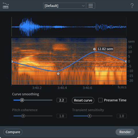
Window Resizing
- Click and drag on the bottom right-hand corner of the module window to customize the window size.
Waveform Display
The single waveform drawn in this panel represents the sum of all enabled channels in the current selection. The waveform drawing is normalized to allow for consistent vertical resolution when working with selections of varying amplitude.
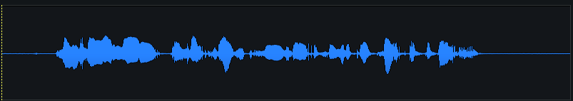
Spectrogram Display
The spectrogram drawn in this panel represents the sum of all enabled channels in the current selection.
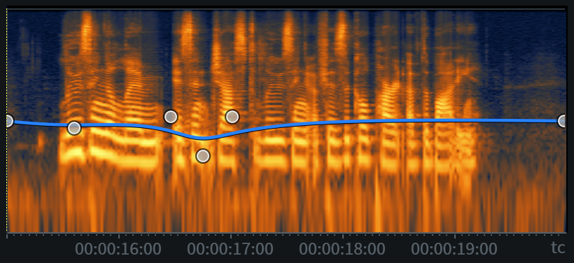
Playhead Indicators
The solid white vertical line and dotted yellow vertical line overlaid on the waveform and spectrogram panels indicate the current playhead position (white) and the playhead anchor position (yellow).
Current Playhead Position
The solid white vertical line overlaid on the waveform and spectrogram panels indicates the current playhead position. This indicator line updates to follow the current playhead position during playback. The playhead position indicator will only appear in the module window when it is within the bounds of the current selection.
Playhead Anchor
The dotted yellow vertical line overlaid on the waveform and spectrogram panels indicates the playhead anchor position in the main editor window. If the playhead anchor position is outside of the current selection bounds, the indicator will not be displayed in the module window.
Contour Curve Display
The blue line overlaid on the spectrogram panel represents the pitch contour curve. Nodes can be added to this curve and adjusted to make changes to pitch over the course of the active selection.
Contour Curve Axes
The contour curve allows for adjustments along two axes: Pitch and Time.
- Pitch: The vertical y-axis of the contour curve represents pitch in semitones.
- The Pitch axis ranges from -24 (bottom) to +24 (top) semitones.
- The center of the Pitch axis equates to 0 semitones.
- The Pitch axis ranges from -24 (bottom) to +24 (top) semitones.
- Time: The horizontal x-axis represents time.
- The time format used here is determined by the time format display selection in the transport section of the main editor window.
- The range of the time ruler matches the length of the current selection.
- The time format used here is determined by the time format display selection in the transport section of the main editor window.
Ruler Zooming
- Hover over the ruler and use a mousewheel or trackpad to zoom in and out.
- Click and drag left or right on the ruler when zoomed in to change the ruler position.
- Double-click on a ruler display to reset the zoom level to default.
Contour Curve Readout
When the cursor is positioned over the spectrogram panel, a text readout will appear in the upper left hand corner of the panel. This readout displays information about the processing that will be applied by the current contour curve.

The readout displays the following information about the current cursor position, from left to right:
- Time: Current time position of the cursor within the spectrogram panel.
- Pitch Shift (%): Percentage of pitch shift that will be applied at the cursor’s current time position.
- Pitch Shift (Semitones): Amount of pitch shift that will be applied at the cursor’s current time position.
Contour Curve Editing
The following section describes the methods and controls available for editing the contour curve.
Add Nodes
Click in the spectrogram panel to add a new node to the contour curve.
Contour Curve Node Limit
- The contour curve supports adding up to 25 nodes.
Semitone Adjustments
Click and drag a node up or down to adjust its semitone value.
Time Adjustments
Click and drag a node left or right to move the associated pitch adjustment point earlier or later in time.
Note
- Nodes cannot be moved outside of the time bounds of the current selection.
- The contour curve shape will be maintained when the selection changes.
- The contour curve shape will be maintained after rendering.
Remove Nodes
Individual nodes can be deleted from the curve using the following methods:
- Click and drag a node past the top or bottom border of the contour curve display to quickly remove it from the curve.
- Control-click (Mac) or ctrl-click (Windows) on a node to remove it from the curve.
Reset Individual Nodes
Double-click on a node to reset it to the default value of 0 semitones. Double-clicking a node only resets the semitone value to default, it will not change the time position of the node.
Reset Curve
Removes all custom nodes from the curve, resetting it to default. Two nodes are present in the default curve, one at the start and one at the end of the current selection. The default nodes are set to 0 semitones (no pitch adjustment).
Smoothing
Adjusts the amount of smoothing applied between nodes on the contour curve. Smoothing is a global control and is applied to all nodes on the curve.
Lower smoothing values: Applies little to no smoothing between nodes on the curve, resulting in strict transitions between nodes.
Higher smoothing values: Applies more smoothing between nodes on the curve, resulting in a gradual, rounded slope between nodes.
Controls
The following section describes the Preserve Time control and the parameters available for refining the results of processing when Preserve Time (Radius Mode) is enabled.
Preserve Time
Determines the pitch processing algorithm that is used when rendering the current selection. When Preserve Time is enabled, the iZotope Radius™ processing algorithm is used. When Preserve Time is disabled, a resampling processing algorithm is used. See the descriptions below for more information about these processing algorithms and how they affect the rendered output.
Preserve Time Disabled (Resampling Mode)
When Preserve Time is disabled, a resampling algorithm is used to render the pitch contour curve. In this mode, time and pitch are adjusted synchronously, as if tape playback speed was adjusted. The length of the rendered selection will change to account for changes in pitch.
- Negative semitone adjustments increase the length of the rendered selection.
- Positive semitone adjustments decrease the length of the rendered selection.
Use Case for Resampling Mode
This mode can be useful for synchronizing two recordings of the same performance that have been captured at slightly different clock speeds.
Preserve Time Enabled (Radius Mode)
When Preserve Time is enabled, the Radius algorithm is used to render the pitch contour curve. The mode will adjust pitch without altering the length of the current selection.
Preserve Time: Additional Controls
- When Preserve Time mode is enabled, additional controls become available for refining the results of processing: Pitch Coherence & Transient Sensitivity.
Pitch Coherence
Adjusts the amount of timbre preservation applied during processing. This control is useful for maintaining the natural timbral qualities of pitched audio content (such as human speech, sung vocals or saxophone) by correcting the smearing or phasing issues that can be introduced during processing.
Increasing pitch coherence can help to combat phase effects that can occur when applying processing to a solo voice or a small group of related instruments. A possible tradeoff of increasing pitch coherence is that it may introduce roughness or unwanted modulation when applying processing to polyphonic or multi-instrument content.
Note
- Pitch Coherence is only available for adjustment when Preserve Time is enabled.
Transient Sensitivity
Adjusts how the Radius algorithm detects and subsequently preserves transient content when processing. Higher values can improve transient clarity at the cost of applying heavier processing to non-transient material. Bowed instruments, such as cello or violin, may present stuttering artifacts after processing with higher transient sensitivity values. Lowering the transient sensitivity value can help to reduce the unwanted artifacts in sustained content.
Transient Sensitivity Control Availability
- Transient Sensitivity is only available for adjustment when Preserve Time mode is ON.
Compare Settings
The Variable Pitch module does not allow for real-time preview playback. To audition different settings before rendering, click the Compare button in the module footer area to send the settings to the Compare Settings window.

Learn more about Compare Settings in the Module Controls chapter.
Alternative Modules
- For pitch envelope editing tailored to speech, try using the Dialogue Contour module in RX 7 Advanced.
- Make static time-stretch and pitch-shift adjustments with the Time & Pitch module.
- Make adjustments to the time stretch ratio envelope of a selection with the Variable Time module.
Variable Time [STD & ADV]
Overview
Variable Time can be used to correct timing issues or creatively adjust speed over the course of a selection. This module leverages the iZotope Radius algorithm to allow for high-quality time compression and expansion without also adjusting pitch.
Displays
Variable Time features a waveform panel and a spectrogram panel that each display information about the current selection in the active file tab. These panels will dynamically update when the selection is changed. If no selection is made in the active file tab, no information will be displayed in the spectrogram or waveform panels.
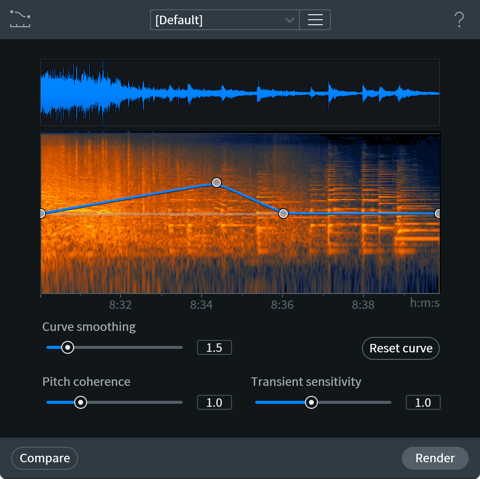
Window Resizing
- Click and drag on the bottom right-hand corner of the module window to customize the window size.
Waveform Display
The single waveform drawn in this panel represents the sum of all enabled channels in the current selection. The waveform drawing is normalized to allow for consistent vertical resolution when working with selections of varying amplitude.
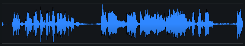
Spectrogram Display
The spectrogram drawn in this panel represents the sum of all enabled channels in the current selection.

Contour Curve Display
The blue line overlaid on the spectrogram panel represents the time stretch ratio contour curve. Nodes can be added to this curve and adjusted to make changes to time stretch ratio over the course of the active selection.
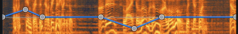
Contour Curve Axes
The contour curve allows for adjustments along two axes: Time Stretch Ratio (y-axis) and Time (x-axis).
- Time Stretch Ratio: The vertical y-axis of the contour curve represents time stretch ratio values in increments associated with both Speed (multiplier) and Length (percentage) adjustments. The effect of adjustments along this axis can be thought of as affecting the processed signal in two ways, adjusting length or adjusting speed. The minimum and maximum values of this axis equate to the following speed and length adjustments:
- Minimum value:
- Speed: 0.125x | 0.125 times slower than the original
- Length: 800.0% | 8 times longer than the original
- Speed: 0.125x | 0.125 times slower than the original
- Maximum value:
- Speed: 8.000x | 8 times faster than the original
- Length: 12.5% | 1/8th the length of the original; 8 times shorter.
- Speed: 8.000x | 8 times faster than the original
- The center of the y-axis is equivalent to no adjustment in length or speed.
- Minimum value:
- Time (Current Selection Length): The horizontal x-axis represents time across the current selection.
- The time format used here is determined by the time format display selection in the transport section of the main editor window.
- The range of the time ruler matches the length of the current selection.
- The time format used here is determined by the time format display selection in the transport section of the main editor window.
Ruler Zooming
- Hover over the ruler and use a mousewheel or trackpad to zoom in and out.
- Click and drag left or right on the ruler when zoomed in to change the ruler position.
- Double-click on a ruler display to reset the zoom level to default.
Contour Curve Readout
When the cursor is positioned over the spectrogram panel, a text readout will appear in the upper left hand corner of the panel. This readout displays information about the processing that will be applied by the current contour curve when it is rendered.

The readout displays the following information about the current cursor position, from left to right:
- Time: Current time position of the cursor within the spectrogram panel.
- Length Adjustment (%): Percentage of length adjustment that will be applied at the cursor’s current time position.
- Speed Adjustment (x - multiplier): Amount of speed adjustment that will be applied at the cursor’s current time position.
Contour Curve Editing
The following section describes the methods and controls available for editing the contour curve.
Add Nodes
Click in the spectrogram panel to add a new node to the contour curve.
Contour Curve Node Limit
- The contour curve supports adding up to 25 nodes.
Time Stretch Ratio Adjustments
Click and drag a node up or down to adjust its time stretch ratio value.
Time Adjustments
Click and drag a node left or right to move the associated time stretch ratio adjustment earlier or later in time.
Note
- Nodes cannot be moved outside of the time bounds of the current selection.
- The contour curve shape will be maintained when the selection changes.
- The contour curve shape will be maintained after rendering.
Remove Nodes
Individual nodes can be deleted from the curve using the following methods:
- Click and drag a node past the top or bottom border of the contour curve display to quickly remove it from the curve.
- Control-click (Mac) or ctrl-click (Windows) on a node to remove it from the curve.
Reset Individual Nodes
Double-click on a node to reset it to the default value of 100%/1.000x (no change to time stretch ratio). Double-clicking on a node will only reset its time stretch ratio value to default, it will not change the time position of the node within the selection.
Reset Curve
Removes all custom nodes from the curve, resetting it to default. Two nodes are present in the default curve, one at the start and one at the end of the current selection. The default nodes are set to 100%/1.000x (no time stretch ratio adjustment).
Smoothing
Adjusts the amount of smoothing applied between nodes on the contour curve. Smoothing is a global control and is applied to all nodes on the curve.
- Lower smoothing values: Applies little to no smoothing between nodes on the curve, resulting in strict transitions between nodes.
- Higher smoothing values: Applies more smoothing between nodes on the curve, resulting in a gradual, rounded slope between nodes.
Controls
The following section describes the controls available for refining the Radius algorithm processing results.
Pitch Coherence
Adjusts the amount of timbre preservation applied during processing. This control is useful for maintaining the natural timbral qualities of pitched audio content (such as human speech, sung vocals or saxophone) by correcting the smearing or phasing issues that can be introduced during processing.
Increasing pitch coherence can help to combat phase effects that can occur when applying processing to a solo voice or a small group of related instruments. A possible tradeoff of increasing this control is that it may introduce roughness or unwanted modulation when processing polyphonic or multi-instrument content.
Transient Sensitivity
Adjusts how the Radius algorithm detects and subsequently preserves transient content when processing. Higher values can improve transient clarity at the cost of applying heavier processing to non-transient material. Bowed instruments, such as cello or violin, may present stuttering artifacts after processing with higher transient sensitivity values. Lowering the transient sensitivity value can help to reduce the unwanted artifacts in sustained content.
Compare Settings
The Variable Time module does not allow for real-time preview playback. To audition different settings before rendering, click the Compare button in the module footer area to send the settings to the Compare Settings window.
Learn more about Compare Settings in the Module Controls chapter.
Alternative Modules
- Make static time-stretch and pitch-shift adjustments with the Time & Pitch module.
- Adjust the pitch envelope over the course of a selection with the Variable Pitch module.
- For pitch envelope editing tailored to speech, try using the Dialogue Contour module in RX 7 Advanced.
Markers & Regions
Overview
Markers and Regions allows you to define and save particular points or selections in time for your audio file. All markers and regions that are created will be saved with your audio file when exporting.
Controls
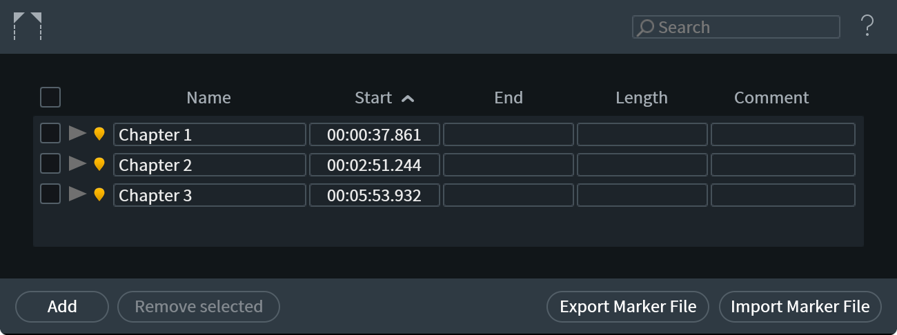
Checkboxes
The checkboxes to the left of your Marker list designate your selection.The checkbox at the top of the list toggles between selecting all and none.
Play Button
Begins playback from the start point of your marker or region.
Find Button
Moves the playhead to the exact position of your marker, but will not begin playback. For a region, Find will select the audio in the region.
Add
Creates a new marker point at the exact current position of the playhead.
Remove Selected
Deletes the desired marker or region.
Select all
Selects all markers and regions.
Select None
Deselects all markers and regions.
Import Marker File
Opens exported marker information from a file.
Export Marker File
Saves markers and regions in a tab-delimited text file that can be opened and used in another file or session of RX.
More Information
- You can add a marker or region at the current location of the playhead by pressing the M key or selecting Add Marker or Region from the Window menu.
- Markers and regions can also be created from the Markers and Regions window.
- If you have a large number of markers and regions, you may use the search box in the upper right to quickly locate the ones you’re looking for.
Spectrum Analyzer
Overview
A spectrum analyzer uses a fast Fourier transform (FFT) to extract frequency information from a waveform. Depending on the size of the FFT, the signal energy of thousands of frequency bands can be visually represented on a graph.
The RX Spectrum Analyzer will show the momentary spectrum of audio around the current playhead position, the average spectrum of a selected time and frequency range, or the real-time spectrum of the audio at the output of RX’s playback.
Controls
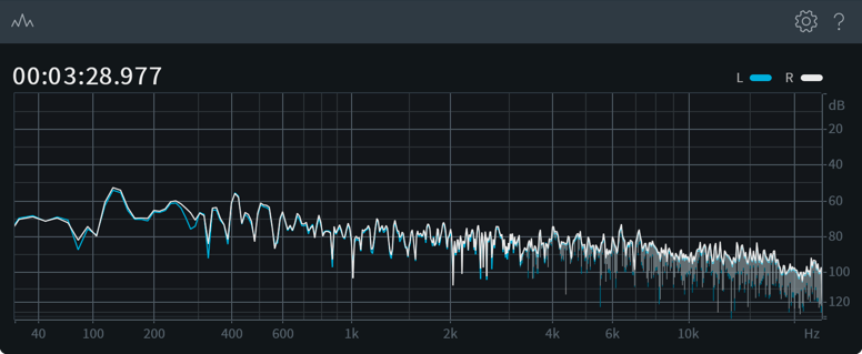
CHANNEL VIEW SELECTION BUTTONS
When viewing the spectrum analyzer of a stereo file, you can toggle the Left or Right channel spectrum display on or off by clicking on the L or R buttons in the upper right hand corner of the spectrum.
PEAK FINDING
The RX Spectrum Analyzer has a peak-finding feature that automatically detects peaks in the spectrum data. If you hover your mouse cursor near a peak in the spectrum, a readout will appear displaying the exact frequency of the peak, its amplitude, and the closest musical note. This peak-finding readout can provide much higher accuracy than simply inspecting the graph by zooming in on the display and/or increasing the FFT size in the settings window.
The circle displays the exact amplitude and frequency of the spectral peak. It is usually slightly above the spectrum, because each spectral peak consists of several FFT bins, and their power is added together. This effect is known as spectral smearing (or frequency smearing) and is controlled by the choice of a weighting window.
Waveform Statistics
Overview
The Waveform Statistics window shows information about the waveform within your current selection. This information can help you find and fix problems like clipping more easily. It is also useful for comparing two similar selections or files.
The Waveform Stats window will update to display information about your active track and can remain open as you switch between track tabs.
Note
- If no selection is made in the active file tab, the Waveform Statistics will populate with values based on the entire file.
- Values that appear in the Waveform Statistics window are based on the full bandwidth of the selection. This means that the Waveform Statistics are gathered based on time selections, and will display values for all frequencies in a time selection, even if the current selection only includes a specific frequency range.
- Selecting the cursor icon next to a value readout will move the playhead to the position in the file where the level was detected.
Controls
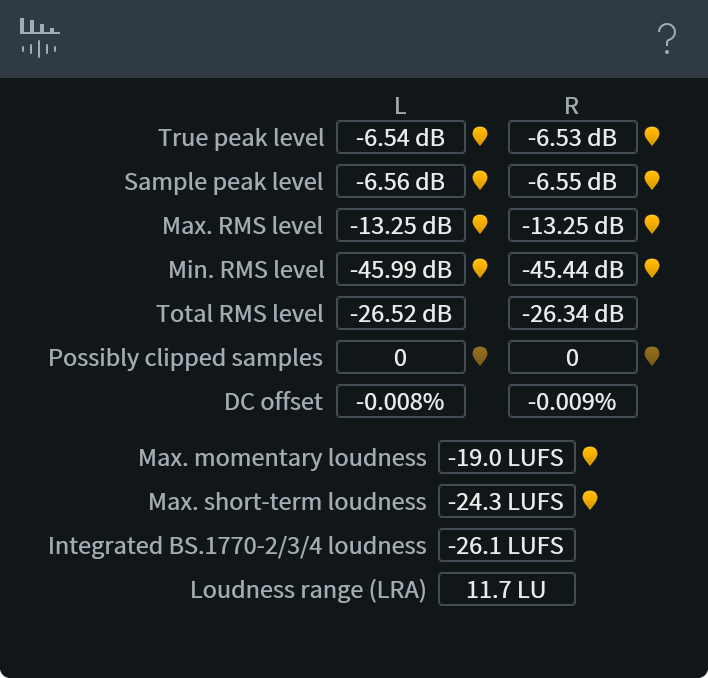
- TRUE PEAK LEVEL: The highest peak level detected, including signal levels between digital samples (called ISPs or Intersample Peaks).
- SAMPLE PEAK LEVEL: The maximum level of digital samples in your selection.
- MAX. RMS LEVEL: The highest RMS level detected in the selection.
- MIN. RMS LEVEL: The lowest RMS level detected in the selection.
- TOTAL RMS LEVEL: The RMS level of the entire selection.
- POSSIBLY CLIPPED SAMPLES: The number of samples where the true peak signal level exceeds 0 dBTP.
- DC OFFSET: The amount of DC offset, in percent of the full scale. Hover this value with your cursor to see this level in decibels.
- MAX. MOMENTARY LOUDNESS: Momentary loudness is computed on a K-weighted audio signal using 400-ms windows, as defined by the BS.1770 specification.
- MAX. SHORT-TERM LOUDNESS: Short-term loudness is computed using 3000-ms windows, as defined by the BS.1770 specification.
- INTEGRATED LOUDNESS: Displays the integrated loudness level (as defined by BS.1770-2). Settings in the Loudness module may switch this field to BS.1770-1 standard.
- LOUDNESS RANGE (LRA): Displays the loudness range (as defined by BS.1770). This value reflects the dynamics of audio levels in the selection.
More Information
- TRUE PEAK: True peak reflects the expected peak level of the analog waveform after digital-to-analog conversion. In practice, it is calculated by oversampling of the digital waveform according to BS.1770-3 standard. Different software may measure true peak levels slightly differently, because the standard leaves some freedom in choice of oversampling filters.
- RMS: RX measures RMS using 50-ms windows (more specifically, a Hann window with a 100-ms period) and references levels using either an AES-17 standard (full-scale sine wave = 0 dB RMS) or a “scientific” standard (full-scale square wave = 0 dB RMS). These RMS measurement standards differ by 3 dB and can be chosen in RX Preferences.
RX Plug-ins
Presets
From the Preset Manager, you can select from default presets and presets you have saved.
To browse presets, press the Presets button and click the name of any preset. If you like what you hear, press the Presets button again to hide the window.
- ADD: Clicking this button adds the current settings as a new preset. You can type a name and optionally add comments for the preset.
Note
- Note that a few keys such as * or / cannot be used as preset names. If you try to type these characters in the name they will be ignored.
- This is because presets are stored as .XML files for easy backup and transferring. Their filenames are the same as the names you give the presets (for easy reference) and therefore characters that are not allowed in Windows file names are not allowed in preset names.
- Note that a few keys such as * or / cannot be used as preset names. If you try to type these characters in the name they will be ignored.
- REMOVE: To permanently delete a preset, select the preset from the list and click the Remove button.
- UPDATE: When you click the Update button, your current settings before you opened the preset window are assigned to the selected preset (highlighted). This is useful for selecting a preset, tweaking it, and saving your changes to the existing preset.
- IMPORT: Imports a preset into the preset folder.
- FOLDER: Opens a dialog that shows your current preset folder. You can also select a new preset folder from this dialog.
- RENAMING PRESETS: You can double click on the name of a preset to enter the edit mode and then type a new name for that preset.
- CANCEL: Press Escape to close the preset system dialog and revert to the settings when you opened the preset manager.
History
Pressing the History button opens the History window. This view gives you a list of all of the actions you’ve performed inside the plug-in, allowing you to step back to previous settings and undo changes.
- CLEAR: Resets the History list.
I/O Meters
- Select plug-ins feature an input and output gain control and input and output metering.
- In stereo instances of the plug-ins, the gain controls are linked stereo gains.
Options
General Options
Authorization & Updates
The Authoriztion and Updates section of the General Options tab includes the following options:
- Updates
- Check now: Opens the iZotope Product Portal application and checks for available updates to RX.
- Check now: Opens the iZotope Product Portal application and checks for available updates to RX.
- Authorization: Learn more in the Authorization chapter.
Host Performance
- View Buffers: Shows buffer information from the host’s track. This is useful for diagnosing problems like audio dropouts or rare problems caused by inconsistent buffer sizes.
- Host Sync: Shows information reported from the host program about playback location, loop and transport state, tempo, etc. (when applicable). This is useful for diagnosing some rare timeline-related problems in specific DAWs.
- Enable Multicore (Spectral De-noise only) This option is available in the Spectral De-noise plug-in. Enabling this option lets RX process Spectral De-noise Quality Modes C and D more efficiently by spreading its processing across multiple computer cores.
I/O Options
The RX I/O meter displays a lower bar representing the average level (RMS) and a higher bar representing peak level. There is also a moving line above the bar representing the most recent peak level or peak hold.
- PEAK HOLD TIME: If peak hold is on, you can choose different peak hold times. The choices are 250 ms, 500 ms, 1000 ms, 5000 ms and Infinite. If set to infinite, the peak value will be held until you click on the current peak display.
- INTEGRATION TIME: Specifies the integration time for RMS calculation. In most RMS meters, the integration time is set to around 300 ms, which makes the RMS meter similar in ballistics to VU meters.
- READOUT: Allows you to control what level value is displayed on top of the meters: peak or actual (real time). If set to Max Peak, the display will show the highest peak level. If set to Current, the display will reflect the meter’s current value.
- ENABLE I/O METERS: Turns the level meters on or off.
- SHOW PEAK HOLD: Turns the peak hold display for the level meters on or off.
Latency
Some of the processing modes in the RX plug-ins are very CPU intensive and result in a delay of the signal. That is, RX needs some time to process the audio before it can send it back to the host application. That time represents a delay when listening or mixing down.
Most modern DAWs and NLEs provide delay compensation—a means for RX plug-ins to tell the application it has delayed the signal, and the host application should “undo” the delay on the track (usually by adding compensating delays to other tracks in real-time processing, or by adjusting the rendered file after processing in offline processing).
When Enable Delay Compensation is enabled in the Latency menu, we will report our latency to the host application.
If your application doesn’t support it, or skips/stutters with this option on, you can always manually correct the delay offset in the host application (manually edit out the short delay of silence). To help you perform manual correction, the delay RX introduces is shown below as Total System Delay in both samples and milliseconds.
RX Monitor
| Plug-in Only |
|---|
Overview
When using the RX Connect plug-in, some DAW/NLEs monopolize the system’s audio drivers, preventing RX from playing audio through the same output device.
The RX Monitor plug-in allows you to listen to the output of the RX Audio Editor through the audio driver output of your host application. This is particularly useful when using RX Connect with a host application that would need to be closed for the RX Audio Editor to access the output driver it is using.
Workflow
- Insert the RX Monitor plug-in on an Aux or Instrument track in your DAW/NLE. When you first insert the RX Monitor plug-in, you will see a “Status: Disconnected” message. You need to configure RX Monitor as the Audio Driver in the RX Audio Editor to change the status to “Connected”

- Change the Audio Driver in the RX Audio Editor:
- Open Preferences
- Select the Audio tab
- In the “Driver Type” dropdown menu, select “RX Monitor”
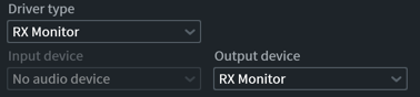
- Open Preferences
- Navigate back to your host application and confirm the RX Monitor plug-in is showing a “Connected” status

- Playback audio in the RX Audio Editor, the output will be routed to the track you added RX Monitor to in your DAW/NLE.
Note
If you are running virus protection software or a firewall on your DAW, you may need to grant permission for RX Monitor to run.
RX Connect
| Plug-in Only |
|---|
Overview
The RX Connect plug-in sends a clip, or multiple clips, to the RX 7 standalone application for editing and repair. This gives you access to all of RX 7’s modules in one place, and provides the benefits of RX’s offline processing and visual interface. RX Connect is available from the AudioSuite menu in Pro Tools, or as an AU or VST plug-in from your host’s effects menu.
Controls
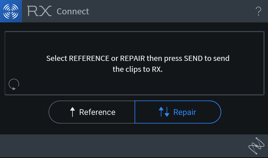
There are two modes for using RX Connect:
- SEND FOR REFERENCE: This is meant for analysis only. The clips are imported into RX 7 but cannot be sent back to your host.
Note about Reference Mode
This mode of RX Connect will not open RX 7 Audio Editor automatically. Opening the Audio Editor after using send for reference will reveal the file in the RX Audio Editor.
- SEND FOR REPAIR: Selected clips are sent to the RX 7 Audio Editor for repair, and you can send them back to your host from the RX Audio Editor.
More Information
- For more information on using RX Connect in different hosts, please refer to the following sections, or refer to the knowledgebase for a more detailed list.
Host Specific Instructions
The following sections outline host specific instructions for using RX Connect to Send audio to the RX Audio Editor and back to your host application:
Adobe Audition CC RX Connect Workflow
- Inside of Audition, select the Waveform view.
- Highlight the area of audio that requires editing.
- In the Effects menu, load the RX 7 Connect plug-in from VST (or VST3) > Restoration> iZotope, Inc. (If you do not see the RX 7 Connect plug-in, open the Audio Plug-in Manager and Scan for Plug-ins, then make sure RX 7 Connect is enabled).
- When the plug-in window opens, click Apply.
- RX 7 will automatically load. Perform your desired audio edit, then click “Send Back” to send the audio back to Adobe Audition. The Waiting for Connect message will appear.
- Re-load the RX 7 Connect plug-in from the Effects menu. It will now display a message “Press Apply to commit changes.” Click Apply to apply the audio edit from RX to your audio file in Adobe Audition.
Avid Media Composer RX Connect Workflow
When using Media Composer, there are two separate workflows for using RX Connect depending on whether you are operating in Master Clip mode or Timeline Mode.
Master Clip Workflow
- Open the AudioSuite Window from the Tools menu
- Drag the Master Clip that you wish to edit onto the AudioSuite Window
- Choose “iZotope RX 7 Connect” from the Plug-in Menu Selection
- Click the purple Activate Current Plug-in button
- Press the SEND button in Media Composer 7.0.x, or Optional in Media Composer 8.1.x to send the audio master clip over to RX
- When you have finished editing your audio in RX, click the “SEND BACK” button
- Back in the AudioSuite Window, press the OK button, and then Render Effect to commit changes
- A new Master clip will now be generated into the designated bin
Timeline Workflow
- Open the AudioSuite Window from the Tools menu
- Select a single audio track in the Timeline, and then choose “iZotope RX 7 Connect” from the Plug-in Menu Selection
- Click the Activate Current Plug-in button
- Press the SEND button in Media Composer to send the audio master clip over to RX.
- When you have finished editing your audio in RX, click “SEND BACK” button
- In the AudioSuite Window press the OK button, and then Render Effect to commit changes
Recommendations
When rendering RX Connect as an AudioSuite effect in Media Composer, the resulting audio will exist in a rendered effect container for the duration of that clip on the timeline. If the clip length is extended beyond those bounds, the rendered effect will become un-rendered, as indicated by a blue dot.
To avoid losing the audio in the rendered effect container, we recommend either:
- Achieve locked picture prior to the audio edit
- Extend the bounds of the clip prior to the audio edit, perform the audio edit with RX Connect, mixdown the clip to a new audio file, and then reduce the bounds back to the original size
- If you make extensive repairs inside of the RX Audio Editor, you can also save an .rxdoc of the file, which will preserve all your adjustments so you can modify them later if you need to.
Monitoring the output of RX Audio Editor
With some audio hardware systems, Media Composer will has control of your audio drivers so that you aren’t able to hear the output of RX.
However, we’ve built the RX Monitor tool to solve just this problem.
- Create a dedicated auxiliary audio track for monitoring RX
- Insert RX Monitor from the “Noise Reduction” or “Sound Field” menus.
- Now, go to the “Preferences” menu in the RX Audio Editor by clicking on the wrench icon in the top-right of the window.
- In the “Audio” tab, set your Driver type to be “RX Monitor.”
- Now you can hear the output of the RX Audio Editor through the audio output chain that Media Composer is using.
Avid Pro Tools RX Connect Workflow
- Choose the audio to be sent to the RX Audio Editor by selecting the audio clip(s) in the timeline that you want to edit, and opening RX Connect from the AudioSuite ‘Noise Reduction’ menu.
- If you just need to load a noise profile or analyze some audio, choose ‘Reference’ to send the audio one-way, but for the complete round-trip workflow click ‘Repair’ and then hit ‘Send’. You’ll see this opens the audio in the RX Audio Editor.
- With HDX systems, Pro Tools will have control of your audio drivers, so you aren’t able to hear the output of the RX Audio Editor. However, the RX Monitor tool is built to solve just this problem. In Pro Tools, create a dedicated aux track for monitoring RX, and insert RX 7 Monitor from the ‘Noise Reduction’ or ‘Sound Field’ menus,
- Then, go to the ‘Preferences’ menu in the RX Audio Editor by clicking on the wrench icon in the top-right of the window. In the ‘Audio’ tab, set your Driver type to be ‘RX Monitor’. Now we can hear the output of the RX Audio Editor through your Pro Tools output chain.
- After you’ve made the desired edits in RX, click ‘Send Back’ at the top of the window. Back at the RX Connect window inside of ProTools, click ‘Render’, and the repaired audio will be placed back into your session.
Tips
- Some engineers might choose to create duplicate playlists before making any repairs to their audio, but you can ‘undo’ these RX Connect changes just like any AudioSuite process.
- If you make extensive repairs inside of the RX Audio Editor, you can also save an .rxdoc of the file, which will preserve all your adjustments so you can modify them later if you need to.
Audiosuite modes:
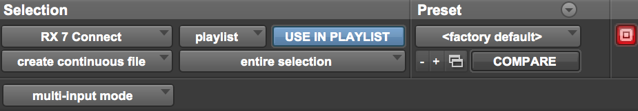
When using Audiosuite plug-ins, there are various user definable input and output options, which affect how you may use RX Connect. These options are:
Input
- Clip-by-clip: Recognizes individual clips in the timeline, as well as fades.
- Entire selection: Treats the entire selected area as one clip.
Modes
- Mono mode: Treats mono, dual mono and stereo clips, as well as multi-channel clips, all as discrete mono clips (e.g. a stereo clip will send as two separate mono files).
Mono mode note
Please note, this can result in large groups of audio clips being sent to RX, potentially exceeding the maximum file limit of 16.
- Multi-input mode Treats dual mono and stereo audio clips as one entity.
Output
- Overwrite files Destructive processing of the audio clip(s) in the session, overwriting the original file with the new file sent from RX.
- Create individual files: Nondestructive processing of the audio file(s) in the session, replacing them with the audio processed in RX. This mode preserves individual clips and fades/handles.
- Create continuous files: Nondestructive processing of the original audio file. Creates a new audio file with the audio sent back from RX, consolidated into one continuous clip.
More Information
For the most up to date information on the expected behaviors when using the recommended configurations, please click here
Steinberg Cubase & Nuendo RX Connect Workflow
- In Cubase/Nuendo, select the audio clip you wish to apply changes to.
- Navigate to the Cubase/Nuendo “Audio” menu and select “Direct Offline Processing”
- In the Direct Offline Processing window, click the ‘+ Plug-in’ button and select RX 7 Connect from the menu that appears.
- After selecting RX 7 Connect from the “+ Plug-in” menu, press ‘Apply’ to send the file to RX. (The file will be automatically sent to RX if the “Auto Apply” option is enabled in Direct OFfline Processing)
- The RX Audio Editor application will automatically open with the file you sent loaded in a tab named “Cubase 1” or “Nuendo 1”.
- Make the desired changes to your file in the RX Audio Editor.
- When you are done making changes to the file, click the ‘Send back’ button in the RX file tab display to send the updated file back to Cubase/Nuendo.
- Click the “Apply” button in the Direct Offline Processing window to apply the changes to the file in the session.
Apply button missing?
If “Auto Apply” is enabled in the Direct Offline Processing window, the “Apply” button will not be available. Disable “Auto Apply” to access the “Apply” button.
Using RX as an External Audio Editor
Some hosts don’t support the use of RX Connect for round-trip editing, please refer to the instructions below for host specific workflows.
Adobe Premiere Pro CC with RX as an external audio editor
- Inside of Premiere, right-click on an audio clip in your timeline and select “Reveal in Finder” (OS X) or “Reveal in Explorer” (Windows).
- Open the resulting file in RX 7 Audio Editor.
- Perform necessary processing in the RX application
- When you have made the desired changes to your file, go to the RX File menu and select Overwrite Original File
Note
- If you have Adobe Audition installed as well, you can right-click on an audio clip in your timeline, and select “Edit Clip In Adobe Audition.” Then follow these steps for using RX Connect with Adobe Audition CC
Apple Final Cut Pro X with RX as an external audio editor
RX is a powerful audio editor that Apple Final Cut Pro X users can use to get better sounding audio in their video projects.
- Select the clip you want to edit in your Final Cut Pro project
- Hit Cmd-Shift-R to Reveal in Finder
- Open the revealed file in RX 7 Audio Editor and make any necessary edits.
- When you are done, in RX choose File>Overwrite Original File to automatically update the clip in your Final Cut Pro project, or File/Export to make a new file, and then import that edited file into Final Cut Pro
Apple Logic Pro X with RX as an external audio editor
RX is a powerful audio editor that Apple Logic Pro X users can use to get better sounding audio. To use RX with Logic, you must first set it up as an external audio editor.
How to set up RX as an external audio editor
- Open Logic Preferences and go to Advanced
- Under Additional options, enable the “Audio” check box.
- In Preferences, click the “Audio” tab and select the “Audio File Editor” tab.
- Under Audio File Editor, click on the External Sample Editor to select RX 7 from your applications folder
Workflow
- Select the clip you wish to edit in your timeline
- Click Edit > “Open in iZotope RX 7 Audio Editor”, [Shift+W]
- The file will open in RX 7. Once you’ve completed your edits, in RX 7 click File > Overwrite Original File
- Close the tab, navigate back to Logic Pro X and wait for the waveform to update
Keyboard Shortcuts
The RX Audio Editor includes options for defining custom keyboard shortcut commands.
The column named “RX Shortcut Command Name” in the table below lists the underlying name associated with each default shortcut in the RX Audio Editor. These are useful to know when assigning custom shortcuts in the Preferences > Keyboard tab.
Importing keyboard shortcuts from RX 6
- If you would like to carry over custom shortcuts you set in RX 6, you will need to export the keybindings from RX 6 and then import that keybindings file to RX 7 using the Import option in the Preferences > Keyboard tab.
| Shortcut | Default Mac Shortcut | Default Windows Shortcut | RX Shortcut Command Name |
|---|---|---|---|
| New… | command+N | ctrl+N | File.New |
| New from Clipboard | shift+command+N | ctrl+shift+N | File.NewFromClipboard |
| Open… | command+O | ctrl+O | File.Open |
| Save | command+S | ctrl+S | File.Save |
| Save As… | shift+command+S | ctrl+shift+S | File.SaveAs |
| Save RX Document | File.SaveRXDocument | ||
| Save RX Document As… | File.SaveRXDocumentAs | ||
| Overwrite Original File | option+command+S | ctrl+alt+S | File.SaveOverwriteOriginal |
| Export… | command+E | ctrl+E | File.Export |
| Export Selection… | shift+command+E | ctrl+shift+E | File.ExportSelection |
| Export Regions to Files… | option+command+E | ctrl+alt+E | File.ExportRegions |
| Close | command+W | ctrl+W | File.Close |
| Close All | shift+V | ctrl+shift+W | File.CloseAll |
| Zoom out full all rulers | command+0 | ctrl+0 | Zoom.AllOutFull |
| Zoom in on amplitude ruler | shift+up arrow | shift+up arrow | Zoom.AmpIn |
| Zoom out on amplitude ruler | shift+down arrow | shift+down arrow | Zoom.AmpOut |
| Zoom in on frequency ruler | shift+command+up arrow | shift+ctrl+up arrow | Zoom.FreqIn |
| Zoom out on frequency ruler | shift+command+down arrow | shift+ctrl+down arrow | Zoom.FreqOut |
| Zoom in on time ruler | up arrow | up arrow | Zoom.TimeIn |
| Zoom in on time ruler | command+= | ctrl+= | Zoom.TimeIn |
| Zoom on left side of time ruler | command+[ | ctrl+[ | Zoom.TimeLeftEdge |
| Zoom out on time ruler | command+- | ctrl+- | Zoom.TimeOut |
| Zoom out on time ruler | down arrow | down arrow | Zoom.TimeOut |
| Zoom out full on time ruler | shift+command+- | ctrl+shift+- | Zoom.TimeOutFull |
| zoom on right side of time ruler | command+] | ctrl+] | Zoom.TimeRightEdge |
| Zoom to time selection | command+ | ctrl+[ | Zoom.TimeSelection |
| Undo | command+Z or option+command+Z | ctrl+Z or ctrl+alt+Z | Edit.Undo |
| Redo | command+Y or shift+command+Z | ctrl+Y or ctrl+shift+Z | Edit.Redo |
| Cut | command+X | ctrl+X | Edit.Copy |
| Copy | command+C | ctrl+C | Edit.Cut |
| Paste | command+V | ctrl+V | Edit.Paste |
| Paste Special> Insert | option+command+V | ctrl+alt+V | Edit.PasteInsert |
| Paste Special> Replace | option+shift+command+V | ctrl+alt+shift+V | Edit.PasteReplace |
| Paste Special> Mix | shift+V | shift+V | Edit.PasteMix |
| Paste Special> Invert and Mix | option+V | alt+V | Edit.PasteMixInvert |
| Paste Special> To Selection Only | option+shift+V | alt+shift+V | Edit.PasteToSelection |
| Paste Special> Clip Gain Only | shift+command+V | ctrl+shift+V | Edit.PasteClipGainOnly |
| Deselect | command+D | ctrl+D | Edit.Deselect |
| Reselect | shift+command+D | ctrl+shift+D | Edit.Reselect |
| Select All | command+A | ctrl+A | Edit.SelectAll |
| Invert Selection | shift+command+I | ctrl+shift+I | Edit.SelectInverse |
| Invert Selection Frequencies | command+I | ctrl+I | Edit.SelectInverseFreq |
| Select Harmonics… | shift+command+H | ctrl+shift+H | Edit.SelectHarmonicsByNumbers |
| Begin Selection At Playhead | [ | [ | Edit.SetSelectionStart |
| End Selection At Playhead | ] | ] | Edit.SetSelectionEnd |
| Delete Selection | Del | Del | Edit.SilenceDelete |
| Trim to Selection | command+T | ctrl+T | Edit.TrimToSelection |
| Snap | shift+command+; | ctrl+shift+; | View.ToggleSnapping |
| Find Similar Event Window | command+F | ctrl+F | Edit.FindSimilarEvent |
| Find Next Similar Event | shift+command+F | ctrl+shift+F | Edit.FindNextSimilarEvent |
| Find Previous Similar Event | option+command+F | ctrl+alt+F | Edit.FindPrevSimilarEvent |
| Add Marker or Region | M | M | Edit.AddMarkerOrRegion |
| Edit Cursor Mode > Select Time | T | T | Edit.EditorCursorMode.SelectTime |
| Edit Cursor Mode > Select Time/Freq | R | R | Edit.EditorCursorMode.SelectTimeFreq |
| Edit Cursor Mode > Select Freq | F | F | Edit.EditorCursorMode.SelectFreq |
| Edit Cursor Mode > Lasso | L | L | Edit.EditorCursorMode.SelectLasso |
| Edit Cursor Mode > Selection Brush | B | B | Edit.EditorCursorMode.SelectBrush |
| Edit Cursor Mode > Selection Wand | W | W | Edit.EditorCursorMode.SelectWand |
| Edit Cursor Mode > Zoom Time | Z | Z | Edit.EditorCursorMode.ZoomTime |
| Edit Cursor Mode > Zoom Time/Freq | shift+Z | shift+Z | Edit.EditorCursorMode.ZoomTimeFreq |
| Edit Cursor Mode > Zoom Freq | option+Z | alt+Z | Edit.EditorCursorMode.ZoomFreq |
| Edit Cursor Mode > Grab Time | G | G | Edit.EditorCursorMode.GrabTime |
| Edit Cursor Mode > Grab Time/Freq | shift+G | shift+G | Edit.EditorCursorMode.GrabTimeFreq |
| Edit Cursor Mode > Grab Freq | option+G | alt+G | Edit.EditorCursorMode.GrabFreq |
| Open Batch Processing window | command+B | ctrl+B | File.BatchProcessing |
| Send Connect Clips back to host | Command+Return | ctrl+return | File.SendConnectClipsBackToHost |
| Discard Connect Clips | command+delete | ctrl+backspace | File.DiscardConnectClips |
| Remove Clip Gain from selection | shift+delete | shift+backspace | Editor.RemoveClipGain |
| Remove All Clip Gain | shift+command+delete | ctrl+shift+backspace | Editor.RemoveAllClipGain |
| Toggle Follow Playhead | command+P | ctrl+P | Transport.TogglePlayheadFollow |
| Toggle Follow Playhead Mode > Page / Continuous | shift+command+P | ctrl+shift+P | Transport.CyclePlayHeadFollowMode |
| Show Clip Gain | command+G | ctrl+G | View.ToggleGainCurveOverlay |
| Show Channels Separately | shift+command+C | ctrl+shift+C | View.ToggleCompositeAudioDisplay |
| Show Spectrogram Settings | shift+command+, | ctrl+shift+, | View.ToggleSpectrogramSettingsVisible |
| Decrease Spectrogram FFT Size | Shift+ | Shift+ | Spectrogram.FFTSizeDecrement |
| Increase Spectrogram FFT Size | Shift+. | Shift+. | Spectrogram.FFTSizeIncrement |
| Show Preferences Window | command+ | ctrl+ | Edit.Preferences |
| Show File Info window | shift+option+command+I | shift+alt+ctrl+I | File.Info |
| Enter Full Screen | ^+command+F | ctrl+^+F | View.ToggleFullScreen |
| Exit Full Screen | esc | Esc | View.ExitFullScreen |
| Toggle Instant Process | I | I | Edit.EditorCursorMode.ToggleInstant |
| Toggle Preview Bypass | shift+B | shift+B | TogglePreviewBypass |
| Toggle Window Opacity | shift+command+O | ctrl+shift+O | View.ToggleFloatingWindowOpacity |
| Toggle Input Monitoring | option+I | alt+I | ToggleInputMonitoring |
| Start or Stop Playback | Spacebar | Spacebar | Transport.PlayOrStop |
| Start or Stop Preview Playback | shift+Spacebar | shift+Spacebar | Transport.PreviewOrStop |
| Rewind Transport | return | Home | Transport.Rewind |
| Seek to End of file | End | Transport.SeekToEnd | |
| Toggle Looping | command+L | ctrl+L | Transport.ToggleLooping |
| Toggle Playhead Follow | command+P | ctrl+P | Transport.TogglePlayHeadFollow |
| Toggle Playhead Return | command+R | ctrl+R | Transport.TogglePlayHeadReturn |
| Select Both Channels | shift+command+B | ctrl+shift+B | Editor.ChannelSelectBoth |
| Select Left Channel | shift+command+L | ctrl+shift+L | Editor.ChannelSelectLeft |
| Select Right Channel | shift+command+R | ctrl+shift+R | Editor.ChannelSelectRight |
| Extend selection left | shift+left Arrow | shift+left arrow | Editor.ExtendSelectionLeft |
| Extend selection left by page | shift+up arrow | shift+page up | Editor.ExtendSelectionPageLeft |
| Extend selection to the right boundary of current view | shift+down Arrow | shift+page down | Editor.ExtendSelectionPageRight |
| Extend selection by increment to the right | shift+right arrow | shift+right arrow | Editor.ExtendSelectionRight |
| Move playhead to next marker or selection boundary | option+right arrow | alt+right arrow | Editor.GoToNextMarkerOrSelectionBoundary |
| Move playhead to previous marker or selection boundary | option+left arrow | alt+left arrow | Editor.GoToPreviousMarkerOrSelectionBoundary |
| Nudge playhead to the left | left arrow | left arrow | Editor.NudgeLeft |
| Nudge playhead to the right | right arrow | right arrow | Editor.NudgeRight |
| Page Left | page up | page up | Editor.PageLeft |
| Page Right | page down | page down | Editor.PageRight |
| Select to End | shift+end | shift+end | Editor.SelectToEnd |
| Select to Start | shift+home | shift+home | Editor.SelectToStart |
| Process Reverse | shift+R | shift+R | Process.Reverse |
| Process Silence | shift+S | shift+S | Process.Silence |
| Process Gain | option+command+6 | ctrl+alt+6 | Apply.Gain |
| Process Leveler | option+command+0 | ctrl+alt+0 | Apply.Leveler |
| Process Loudness | option+command+4 | ctrl+alt+4 | Apply.Loudness |
| Process Ambience Match | option+command+2 | ctrl+alt+2 | Apply.MatchAmbience |
| Process Mixing | option+command+8 | ctrl+alt+8 | Apply.ChannelMix |
| Process De-plosive | command+5 | ctrl+5 | Apply.DePlosive |
| Process De-click | command+2 | ctrl+2 | Apply.Declick |
| Process De-clip | command+1 | ctrl+1 | Apply.Declip |
| Process Deconstruct | command+7 | ctrl+7 | Apply.Deconstruct |
| Process De-reverb | command+8 | ctrl+8 | Apply.Dereverb |
| Process EQ | option+command+7 | ctrl+alt+7 | Apply.EQ |
| Process EQ Match | option+command+1 | ctrl+alt+1 | Apply.EQMatch |
| Process Plug-in | option+command+5 | ctrl+alt+5 | Apply.Plug-in |
| Process De-Hum | command+3 | ctrl+3 | Apply.RemoveHum |
| Process Resampler | option+command+9 | ctrl+alt+9 | Apply.Resampler |
| Process Spectral Repair | command+6 | ctrl+6 | Apply.SpectralRepair |
| Process Pitch Contour | option+command+3 | ctrl+alt+3 | Apply.TimeStretchPitchShift |
| Process Voice De-noise | command+4 | ctrl+4 | Apply.VoiceDenoise |
| Open Gain module | shift+option+6 | shift+option+6 | View.Module.ToggleGain |
| Open Leveler module | shift+option+0 | shift+option+0 | View.Module.ToggleLeveler |
| Open Loudness module | shift+option+4 | shift+option+4 | View.Module.ToggleLoudness |
| Open Ambience Match module | shift+option+2 | shift+option+2 | View.Module.ToggleMatchAmbience |
| Open Mixing module | shift+option+8 | shift+option+8 | View.Module.ToggleChannelMix |
| Open De-plosive module | shift+5 | shift+5 | View.Module.DePlosive |
| Open De-click module | shift+2 | shift+2 | View.Module.ToggleDeclick |
| Open De-clip module | shift+1 | shift+1 | View.Module.ToggleDeclip |
| Open Deconstruct module | shift+7 | shift+7 | View.Module.ToggleDeconstruct |
| Open De-reverb module | shift+8 | shift+8 | View.Module.ToggleDereverb |
| Open EQ module | shift+option+7 | shift+option+7 | View.Module.ToggleEQ |
| Open EQ Match module | shift+option+1 | shift+option+1 | View.Module.ToggleEQMatch |
| Open Plug-in window | shift+option+5 | shift+option+5 | View.Module.TogglePlugIn |
| Open De-hum module | shift+3 | shift+3 | View.Module.ToggleRemoveHum |
| Open Resample module | shift+option+9 | shift+option+9 | View.Module.ToggleSRC |
| Open Spectral Repair module | shift+6 | shift+6 | View.Module.ToggleSpectralRepair |
| Open Time & Pitch module | shift+option+3 | shift+option+3 | View.Module.ToggleTimeStretchPitchShift |
| Open Voice De-noise module | shift+4 | shift+4 | View.Module.ToggleVoiceDenoise |
| Open Markers window | option+m | option+m | View.ToggleMarkerPanelVisible |
| Open Module Chain window | c | c | View.ToggleModuleChainVisible |
| Open Spectrum Analyzer window | option+r | option+r | View.ToggleSpectrumAnalyzerVisible |
| Open Waveform Stats window | option+d | option+d | View.ToggleWaveformStatsVisible |
| Learn Ambience Match | shift+option+command+9 | shift+alt+ctrl+9 | Apply.DereverbTrain |
| Suggest De-hum | shift+option+command+4 | shift+alt+ctrl+4 | Apply.RemoveHumTrain |
| Learn Voice De-noise | shift+option+command+5 | shift+alt+ctrl+5 | Apply.VoiceDenoiseTrain |
| Learn EQ Match | shift+option+command+2 | shift+alt+ctrl+2 | Apply.EQMatchTrain |
Identifying Audio Problems
As with medical diagnostics, the key to successful audio restoration lies in your ability to correctly analyze the subject’s condition. This can be a life-long, never-ending quest, constantly honing the ear to distinguish the noises and audio events that need to be corrected.
RX Processing Step Flowchart
To get started, it’s important to identify the problems with your file and select the tool(s) that will give you the best results. We have created a process flowchart to help identify the right RX module to use and what modules to consider using if you aren’t getting the results you are looking for.
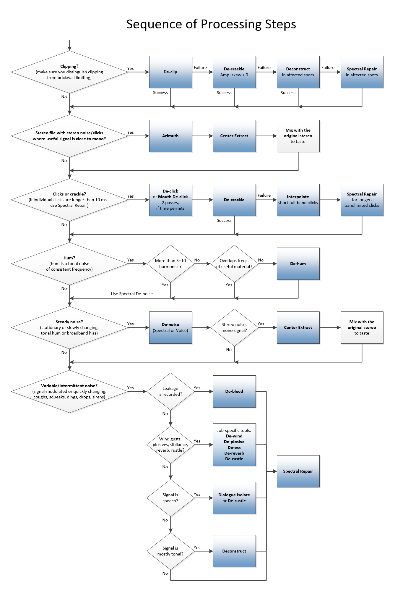
Using the Spectrogram Display
Let’s briefly look at how to examine your audio using the spectrogram and waveform display tools, then consider how to identify audio problems using these displays.
The aim of any good visualization tool for audio repair and restoration is to provide you with more information about an audible problem. This not only helps inform your editing decisions, but, in the case of a spectrogram display, can provide new, exciting ways to edit audio, especially when used in tandem with a waveform display.
Hum
Hum is usually the result of electrical noise somewhere in the recorded signal chain. It’s normally heard as a low-frequency tone based at either 50 Hz or 60 Hz depending on where the recording was made If you zoom in to the low frequencies, you’ll be able to see hum as a series of horizontal lines, usually with a bright line at 50 Hz or 60 Hz and several less intense lines above it at harmonics. See the example below:

De-hum works best when frequencies of the hum do not overlap with any useful transient signals. You can learn more about the De-hum tool here.
Buzz
In some cases, electrical noise will extend up to higher frequencies and manifest itself as a background buzz. See the example below:
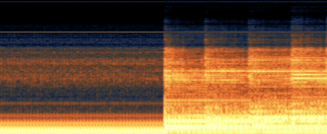
Hum-removal tools usually focus on low-frequency hum, so when the harmonics extend to frequencies above 400 Hz, the Spectral De-noise tool is often more effective at removing the problem.
Hiss and other Broadband Noise
Unlike hum and buzz, broadband noise is spread throughout the frequency spectrum and isn’t concentrated at specific frequencies. Tape hiss and noise from fans and air conditioners are good examples of broadband noise. In a spectrogram display, broadband noise usually appears as speckles that surround the program material. See the example below:
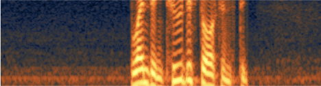
Clicks, Pops, & Short Impulse Noises
Clicks and pops are common on recordings made from vinyl, shellac and other grooved media, but can also be introduced by digital errors, including recording into a DAW with improper buffer settings, or making a bad audio edit that missed a zero crossing. Even mouth noises such as tongue clicks and lip smacks fall into the clicks category. These short impulse noises appear in a spectrogram as vertical lines. The louder the click or pop, the brighter the line will appear. The example below shows clicks and pops appearing in an audio recording transferred from vinyl:
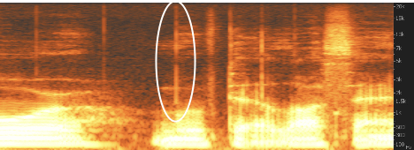
The De-click tool can recognize, isolate, and then reduce and remove clicks like these.
Clipping
Clipping is an all-too-common problem. It can occur when a loud signal distorts the input to an audio interface, analog-to-digital converter, mixing console, field recorder, or other sound capture device. A spectrogram is not particularly useful for identifying clipped audio—for this you’ll want to work with a waveform display. As you’ll see in the image below, the clipping appears as “squared-off” sections of the waveform.
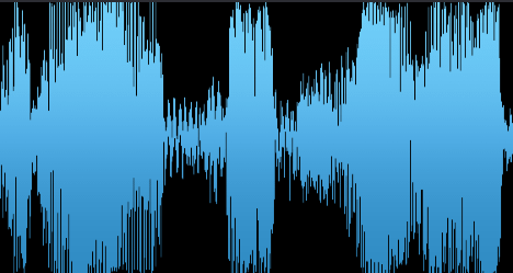
You can zoom in on a waveform and see in detail where the waveform has been truncated because of clipping.
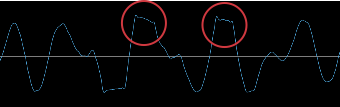
The De-clip tool can intelligently redraw the waveform to where it might have naturally been if the signal hadn’t clipped. Sometimes, brickwall limited audio will also appear “squared off” when zoomed out, but this doesn’t necessarily mean it will sound as heavily distorted as clipped waveforms that have been truncated. You can zoom in to see if the tops of individual waveforms are clipped.
Intermittent Noises
Intermittent noises are different than hiss and hum—they may appear infrequently and may not be consistent in pitch or duration. Common examples include coughs, sneezes, footsteps, car horns, ringing cell phones, etc. The images below represent two different examples of these noises:
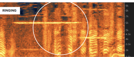
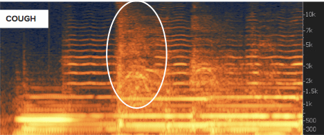
The Spectral Repair tool can help isolate these intermittent sounds, analyze the audio around them and attenuate or replace them.
Gaps and Drop Outs
Sometimes a recording may have short sections of missing or corrupted audio. These are usually very obvious to both the eye and the ear! See the example below:
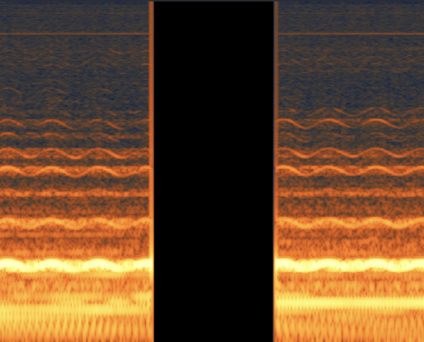
Deleting the gap and then applying Spectral Repair to replace any missing audio can help fix these problems.
Authorization
Overview
The first time you open the RX 7 Audio Editor application or RX 7 plug-in(s), the Authorization window will appear.
The Authorization window allows you to:
- TRIAL: Start or continue a Trial period evaluation prior to purchasing
- DEMO: Continue evaluating the product with Demo limitations (after the 30 day Trial period has been exceeded)
- AUTHORIZE: Authorize the product with a serial number
Trial & Demo Modes
A 30 day trial period will start when you first open the RX 7 Audio Editor or RX 7 plug-ins. After the 30 day trial period has expired, RX 7 will enter demo mode. To disable Trial or Demo mode, you must authorize the product with a valid serial number.
Trial Mode
Trial mode begins when the RX Audio Editor is first opened or when an RX 7 plug-in is first instantiated in a DAW/NLE. The authorization wizard window will display the number of days remaining in your trial period.
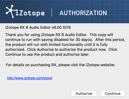
Clicking on the “Continue” button will dismiss the Authorization window and allow you to continue evaluating RX 7 in trial mode.
Trial Mode Functionality
- The RX 7 plug-ins offer full functionality during the 30 day Trial period.
- The RX 7 Audio Editor offers full access to all editing tools and processing modules but saving, exporting and batch processing are not available during the 30 day Trial period.
Demo Mode
After 30 days, RX 7 will operate in Demo mode. In Demo mode, the RX 7 Audio Editor is limited to 30 seconds of continuous playback and RX 7 plug-ins will periodically output silence. If you would like to continue evaluating RX 7 in demo mode, click the “Demo” button.
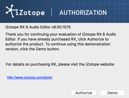
Authorizing RX 7
We offer three main methods for authorizing RX 7:
- Online Authorization: Use this method to authorize RX 7 on a machine that is connected to the internet.
- Offline Authorization: Use this method to authorize RX 7 on a machine that is not connected to the internet.
- iLok Authorization: Use this method to authorize RX 7 using an iLok.
The following sections explain how to authorize RX 7 using the different methods.
Advanced Authorization Options
Clicking the Advanced button in the authorization screen reveals a set of options that allow you to store your RX 7 authorization on a portable hard drive or flash drive. More details on advanced authorization can be found on the iZotope website: www.izotope.com/en/support/authorization/
Online Authorization
To authorize RX 7 on a computer that is connected to the internet:
- Click on “Authorize”
The following screen will appear:

You must enter your name and a valid email address.
Why is an email address required to authorize?
- Authorizations are associated with a user account on the iZotope website. Please make note of the email address you use in this screen, it will be directly linked to an iZotope account upon successful authorization.
- If you do not already have an iZotope account associated with the email address you enter in the authorization window, an iZotope account will automatically be created and associated with that email address when the product is successfully authorized. It is useful to keep track of the email you use in this screen to ensure that you are able to easily login to your iZotope account in the future (for example, to access product update downloads)
- If you already have an iZotope account associated with that email address, the authorization will be associated with the existing account.
- If you do not already have an iZotope account associated with the email address you enter in the authorization window, an iZotope account will automatically be created and associated with that email address when the product is successfully authorized. It is useful to keep track of the email you use in this screen to ensure that you are able to easily login to your iZotope account in the future (for example, to access product update downloads)
- Authorizations are associated with a user account on the iZotope website. Please make note of the email address you use in this screen, it will be directly linked to an iZotope account upon successful authorization.
Enter the serial number, using all capital letters, as it is shown in your purchase confirmation email. SN-RX7-XXXX-XXXX-XXXX-XXXX
When you have confirmed that your serial number and email information is accurate, click once more on “Authorize.”
Click on “Submit” to send your authorization information to iZotope.
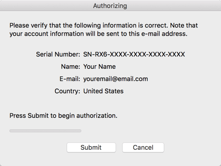
Once the authorization is accepted, click on the Finish button to complete the authorization.
Offline Authorization
If you are installing RX 7 on a machine that is not connected to the internet, you can use the Offline Authorization option to successfully authorize RX 7.
Follow these steps to authorize RX 7 offline:
- Click on “Authorize” in the first screen of the Auth Wizard
- Click the “Offline Authorization” button that appears on the bottom half of the screen. This will open the following window:
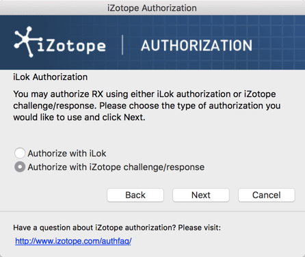
- Select the “Authorize with iZotope challenge/response” option, and click “Next” to proceed
- The next window that appears contains a unique challenge code that is specific to your machine.
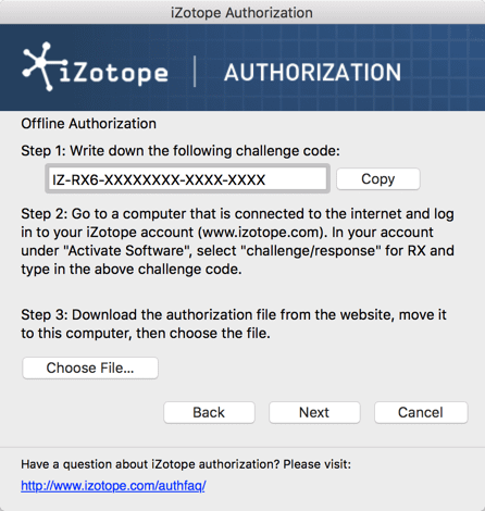
Write down or make a copy of your unique challenge code, you will need to enter this exact code in step 9. - Using a system with Internet access, login to your iZotope customer account: www.izotope.com/en/account/log-in/
- Once you are logged in, Select “Activate Software with a Serial Number”
- Enter your full serial number (obtained after purchasing the product) and click “Submit” Enter your serial number in this step, not the Challenge Code. The Challenge code will be entered in step 9.
- Select the “Challenge/Response” option and click “Submit”
- Enter your unique Challenge Code (from step 4) and click “Submit”
- After submitting your Challenge Code, you will receive a unique authorization file. The auth file will have a name similar to: “iZotope_RX_7_xxxxx.izotopelicense”
- Download this file to your machine.
- Move the .izotopelicense file to a portable storage device (ie. flash drive) or local network drive.
- Transfer the .izotopelicense file from your storage device or local network drive to your offline computer.
- Open RX and return to the screen from step 4 (if it is not already open). Select the “Choose File…” button.
- In the system window that appears, find and select the .izotopelicense file you transferred to the offline machine and click “Next” to authorize.
- If authorization was successful, a confirmation screen will appear. Click “Finish” to begin using RX 7.
iLok Authorization
iLok authorization note
RX 7 supports the use of iLok for authorization if you have the iLok License Manager installed on your system. RX does not install the iLok License Manager (or any iLok drivers) during installation. Please visit the iLok website to download and install the iLok License Manager if you wish to store your RX authorization on an iLok.
Follow these steps to authorize RX 7 using an iLok:
- When the Authorization Wizard appears, choose “Authorize”
- Enter the serial number in all capital letters as it is shown on the included card or purchase confirmation email.
- This would look something like: SN-RX7-XXXX-XXXX-XXXX-XXXX
- This would look something like: SN-RX7-XXXX-XXXX-XXXX-XXXX
Enter your name and a valid email address.
Why is an email address required to authorize?
- Authorizations are associated with a user account on the iZotope website. Please make note of the email address you use in this screen, it will be directly linked to an iZotope account upon successful authorization.
- If you do not already have an iZotope account associated with the email address you enter in the authorization window, an iZotope account will automatically be created and associated with that email address when the product is successfully authorized. It is useful to keep track of the email you use in this screen to ensure that you are able to easily login to your iZotope account in the future (for example, to access product update downloads)
- If you already have an iZotope account associated with that email address, the authorization will be associated with the existing account.
- If you do not already have an iZotope account associated with the email address you enter in the authorization window, an iZotope account will automatically be created and associated with that email address when the product is successfully authorized. It is useful to keep track of the email you use in this screen to ensure that you are able to easily login to your iZotope account in the future (for example, to access product update downloads)
- Authorizations are associated with a user account on the iZotope website. Please make note of the email address you use in this screen, it will be directly linked to an iZotope account upon successful authorization.
Select “Use iLok Authorization” and enter your iLok ID. If you do not have an iLok ID, you will need to create one. Entering an ID in this field will not create a new iLok account. Please visit the iLok website for information on creating an iLok ID.

When you have confirmed that your information is accurate, click on “Authorize.”
Click on “Submit” in order to send your authorization message to the iZotope servers.
You will now be instructed to log in to your iLok account and transfer your RX 7 Audio Editor license to your iLok.
After transferring the authorization to your iLok, ensure the iLok is plugged into your machine and click “Next”
If authorization was successful, a confirmation screen will appear. Click “Finish” to begin using RX 7.
Removing Authorization
Use the Remove Authorization button in the RX 7 Audio Editor’s Auth & Updates tab within the Preferences to remove your current RX 7 Audio Editor authorization.
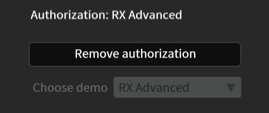
Note for iLok users attempting to remove authorization
Remove the iLok containing an RX 7 license from your machine in order to remove authorization.
After removing your authorization, RX 7 Audio Editor’s authorization screen will pop up when you restart the program. Now you can re-authorize using a new serial number. You may also remove your authorization at any time in order to run in Trial or Demo mode.
Contacting iZotope Customer Care
For additional help with authorizing RX 7 Audio Editor:
- Check out the Customer Care pages on our website: http://www.izotope.com/support
- Contact our Customer Care department at support@izotope.com
For more information on iZotope’s Customer Care department and policies can be found in the iZotope Customer Care section.
iZotope Customer Care
How to purchase the full version of RX 7 Audio Editor
If you are using the demo version of RX 7 Audio Editor and would like the full version, you can purchase RX 7 Audio Editor direct from the iZotope online store: www.izotope.com/store
Once your purchase is complete, you will be sent an email confirmation and a full version serial number that can be used to fully authorize your current installation of RX 7 Audio Editor.
iZotope Customer Care Policy
iZotope is happy to provide professional technical Customer Care to all registered users absolutely free of charge.
Contact iZotope Customer Care
We also offer valuable pre-sales technical Customer Care to customers who may be interested in purchasing an iZotope product. Before contacting iZotope Customer Care, you can search our Product Knowledgebase to see if the solution to your problem has already been published.
How long does iZotope provide customer support for purchased products?
You can email us with any question for 12 months after you buy any iZotope product. Past 12 months, we’ll still help you with your account and authorization but will not provide technical support for in-depth product questions. If you need more detailed help on how to use the product, please check out our FAQs and Tutorials.
How long does iZotope support its products?
Although we can’t guarantee it, we do our best to keep our products up to date with the operating systems and plug-in hosts that we support. Sometimes, other companies make changes that we’re not able to support, but we actively work with other companies to avoid these sorts of compatibility problems. We also do our best to address bug fixes within the product itself to ensure our products operate in accordance with our specifications.
We will provide software updates for 12 months from product release. After 12 months, no software updates will be provided.
For details on what operating systems and plug-in host software are officially supported for a product, please check that product’s specs page.
Contacting iZotope Customer Care
For additional help with RX 7 Audio Editor:
- Check out the Customer Care pages on our web site at www.izotope.com/support
- Contact our Customer Care department at support@izotope.com
iZotope’s highly trained Customer Care team is committed to responding to all requests within one (1) business day and frequently respond faster. Please try to explain your problem with as much detail and clarity as possible. This will ensure our ability to solve your problem accurately, the first time around. Please include all system specs and the build/version of RX 7 Audio Editor that you are using.
Once your Customer Care request is submitted, you will receive a confirmation email from iZotope Customer Care. If you do not receive this email within a few minutes, please check your spam folder and make sure our responses are not getting blocked. To prevent this from happening please add support@izotope.com to your list of allowed email addresses.
International Distribution
Customer Care is also available from our international distributors worldwide for any customers who purchased their iZotope products through a certified iZotope distributor.
Check with your local distributor for availability. If you would like help locating your local distributor please contact iZotope Customer Care.
Thanks for using RX 7 Audio Editor!
- The iZotope Team
EULA
END USER LICENSE AGREEMENT
READ CAREFULLY THE TERMS AND CONDITIONS OF THIS AGREEMENT (“AGREEMENT”) BEFORE YOU CLICK ON THE “ACCEPT” BUTTON OR OTHERWISE USE THE PRODUCT. CLICKING ON THE “ACCEPT” BUTTON OR OTHERWISE DOWNLOADING, INSTALLING AND/OR USING THE LICENSED SOFTWARE OR ANY TECHNOLOGY, IDEA, DATA AND DATABASES, ALGORITHM OR INFORMATION CONTAINED THEREIN OR PROVIDED THEREWITH (COLLECTIVELY, THE “SOFTWARE”), ESTABLISHES A BINDING AGREEMENT BETWEEN YOU AS THE PERSON LICENSING THE SOFTWARE, EITHER ON BEHALF OF YOURSELF OR ANY THIRD PARTY ENTITY (“YOU” OR “LICENSEE”) AND IZOTOPE, INC. (“IZOTOPE”), YOU (WHETHER AN INDIVIDUAL OR FORMAL LEGAL ENTITY) (HEREINAFTER REFERRED TO AS “YOU”), AGREE TO BE BOUND BY THE TERMS AND CONDITIONS OF THIS AGREEMENT WITH RESPECT TO YOUR USE OF THE SOFTWARE.
BY INSTALLING AND/OR BY USING THE SOFTWARE, YOU REPRESENT AND WARRANT THAT YOU HAVE THE LEGAL CAPACITY AND AUTHORITY TO ENTER INTO A BINDING AGREEMENT TO ADHERE TO THE TERMS AND CONDITIONS SET FORTH HEREIN, AND THAT THE SOFTWARE WILL BE USED ONLY IN ACCORDANCE WITH THESE TERMS AND CONDITIONS AND WITH ALL APPLICABLE LAWS. IF AN INDIVIDUAL IS REGISTERING OR USING THE SOFTWARE ON BEHALF OF AN ENTITY OR ORGANIZATION, THAT INDIVIDUAL WARRANTS, REPRESENTS, AND COVENANTS TO IZOTOPE THAT SUCH INDIVIDUAL IS DULY AUTHORIZED TO AGREE TO THESE TERMS AND CONDITIONS ON BEHALF OF THE ORGANIZATION AND TO BIND THE ORGANIZATION TO THEM.
LICENSE. Subject to all the terms and conditions of this Agreement, iZotope hereby grants to Licensee a license to use the Software accompanying this Agreement, as well as any presets and documentation provided, whether in printed, “online” or electronic form, either on a stand-alone computer or on a network, on any one computer at any one time. If more than one user will be using the Software at any one time, you must obtain from iZotope additional license(s) for each additional concurrent user of the Software. The Software is “in use” on a computer when loaded into memory (RAM). You may make one copy of the Software solely for backup or archival purposes if all copyright and other notices are reproduced on that copy, or you may copy the Software to a single hard disk provided you keep the original solely for backup or archival purposes. If the Software is an upgrade, you must have a license for the Software from which it is upgraded. If you receive the Software in more than one media, that does not affect the number of licenses you are receiving or any other term of this Agreement.
OWNERSHIP. The copyrights, patents, trade secrets, trademarks, and all other intellectual property rights in the Software and documentation (including any images, photographs, animations, video, audio, music and text incorporated in them) are owned by iZotope or its suppliers and are protected by the copyright, patent and other laws of the United States and other countries and by international treaty provisions. iZotope retains all rights not expressly granted in this Agreement. You shall not remove any product identification, trademark, copyright or other notices contained in or on the Software.
OTHER RESTRICTIONS. You may not modify, adapt, decompile, disassemble or otherwise reverse engineer the Software, except to the extent this restriction is expressly prohibited by applicable law, nor may you create derivative works based upon the Software, or to permit third parties to do so. You may not loan, rent, lease, or license the Software, or use the Software as a service bureau, as an application service provider, to perform consulting or training services for a third party or in any commercial time share arrangement, but you may permanently transfer your rights under this Agreement provided you transfer this Agreement, the Software, and all accompanying printed materials and retain no copies, and the recipient agrees to the terms of this Agreement. Any such transfer must include the most recent update and all prior versions.
LIMITED WARRANTY. iZotope warrants that, for a period of thirty (30) days from the date the Software is made available to you for download, the Software will substantially conform to the applicable user documentation provided with the Software. Any implied warranties which may exist despite the disclaimer herein will be limited to thirty (30) days (“Warranty Period”). This limited warranty is void if you buy from an unauthorized reseller, you violate the terms of this Agreement, or if the failure of the Software is due to accident, abuse or misapplication. Some states/jurisdictions do not allow limitations on duration of an implied warranty, so this limitation may not apply to you.
YOUR REMEDIES. iZotope’s sole obligation and your exclusive remedy for any breach of warranty will be, at iZotope’s sole option, either the return of the purchase price you paid or the repair or replacement of the Software, media and documentation, provided you in all instances return the Software, together with all media and documentation and a copy of your receipt, to the location where you obtained it during the Warranty Period. Outside the United States, neither these remedies nor any support services are available without proof of purchase from an authorized non-U.S. source.
SUPPORT. Subject to the limited warranty stated above, and further subject to you not being in violation of any term of this Agreement, iZotope will provide email support for the Software to the original purchaser, for a period of 12 months from the original purchase date.
REGISTRATION INFORMATION. When you activate the Software, iZotope may collect your name and email address and other contact information you choose to provide. IZotope may use this information to contact you regarding upgrades and new products. iZotope does not collect or retain any financial information (such as credit card information).
USAGE INFORMATION. When you activate and/or use the Software, iZotope may collect certain information about your computer and your interaction with the Software via the internet (“Usage Information”). Usage Information is information on how you interact with the Software, and is then utilized by iZotope for statistical analysis for improving the Software, and to provide you with a more relevant user experience. No direct personal information or audio files/samples are collected as part of this Usage Information. Usage Information is generally collected in the aggregate form, without identifying any user individually, although IP addresses, computer and session ids in relation to purchases and downloads/installations of the Software may be tracked as part of iZotope’s customer order review, statistical analysis, and fraud and piracy prevention efforts. This Usage Information may be sent to an iZotope web or third-party cloud server for storage or further processing by iZotope and/or its partners, subsidiaries or affiliates, including, but not limited to, Google Analytics. The Software includes an opt-out provision if you do not wish to provide iZotope with such Usage Information.
DISCLAIMER. THE SOFTWARE IS PROVIDED “AS IS.” TO THE MAXIMUM EXTENT PERMITTED BY APPLICABLE LAW, EXCEPT FOR THE EXPRESS WARRANTY SET FORTH HEREIN, IZOTOPE DISCLAIMS ALL OTHER WARRANTIES, EXPRESS OR IMPLIED, INCLUDING BUT NOT LIMITED TO THE IMPLIED WARRANTIES OF NON-INFRINGEMENT, MERCHANTABILITY AND FITNESS FOR A PARTICULAR PURPOSE. IZOTOPE DOES NOT WARRANT THAT THE SOFTWARE WILL MEET YOUR REQUIREMENTS OR THAT THE SOFTWARE WILL OPERATE UNINTERRUPTED OR ERROR-FREE. THE WARRANTY AND REMEDIES SET FORTH HEREIN ARE EXCLUSIVE AND IN LIEU OF ALL OTHERS, ORAL OR WRITTEN, EXPRESS OR IMPLIED. No dealer, distributor, agent or employee of iZotope is authorized to change or add to the warranty and remedies set forth herein. Any other software furnished with or accompanying the Software is not warranted by iZotope.
LIMITATION OF LIABILITY. TO THE MAXIMUM EXTENT PERMITTED BY APPLICABLE LAW, IN NO EVENT WILL IZOTOPE BE LIABLE FOR ANY AMOUNTS EXCEEDING THE AMOUNTS RECEIVED FROM YOU FOR YOUR LICENSE OF THE SOFTWARE, REGARDLESS OF THE FORM OF ACTION, AND WHETHER ARISING OUT OF THE USE OF OR INABILITY TO USE THE SOFTWARE (INCLUDING, WITHOUT LIMITATION, DAMAGES OR COSTS FOR LOSS OF PROFITS, BUSINESS, GOODWILL, DATA OR OTHER ASSETS, OR COMPUTER PROGRAMS) EVEN IF IZOTOPE HAS BEEN ADVISED OF THE POSSIBILITY OF SUCH DAMAGES. Some jurisdictions do not allow exclusion or limitation of liability for consequential or incidental damages, so this limitation may not apply to you.
TERMINATION. The Agreement will terminate automatically if you fail to comply with any of its terms. On termination, you must immediately cease using and destroy all copies of the Software.
LICENSES TO U.S. GOVERNMENT. This paragraph applies to all acquisitions of the Software by or for the federal government, or by any prime contractor or subcontractor (at any tier) under any contract, grant, cooperative agreement or other activity with the United States government (collectively, the “Government”). By clicking “I ACCEPT”, you are agreeing on behalf of the Government that the Software and any documentation related thereto are respectively “commercial computer software” and “commercial computer software documentation” within the meaning of the acquisition regulation(s) applicable to this procurement. These terms and conditions alone will govern the Government’s use of the Software and will supersede any conflicting contractual terms or conditions. If the license granted by these terms and conditions fails to meet the Government’s needs or is inconsistent in any respect with Federal law, the Government must return the Software unused to iZotope. Contractor/Manufacturer is iZotope, Inc., 60 Hampshire Street, Cambridge, MA 02139.
GENERAL. The export of the Software from the United States and re-export from any other country is governed by the U.S. Department of Commerce under the export control laws and regulations of the United States and by any applicable law of such other country, and the Software may not be exported or re-exported in violation of any such laws or regulations. This Agreement is the complete and exclusive statement of the agreement between you and iZotope and supersedes any proposal or prior agreement, oral or written, and any other communications relating to the subject matter of this Agreement. This Agreement will be governed by and interpreted under the laws of the Commonwealth of Massachusetts, United States of America, without regard to conflicts of law provisions. The application of the United Nations Convention of Contracts for the International Sale of Goods is expressly excluded. This Agreement is in the English language only, which language will be controlling in all respects, and all versions of this Agreement in any other language will be for accommodation only.
IN ADDITION, ANY SUCH LEGAL PROCEEDING SHALL NOT BE HEARD BEFORE A JURY. EACH PARTY GIVES UP ANY RIGHT TO A JURY TRIAL. To the extent permitted by law, you agree that you will not bring any class action lawsuit against iZotope or be a representative plaintiff or plaintiff class member in any such lawsuit.
Should you have any questions about this Agreement or iZotope’s software use policies, or if you desire to contact iZotope for any other reason, in the U.S., please email sales@izotope.com; outside the U.S., please contact the iZotope representative or affiliate serving your country or, if you are unsure whom to contact, iZotope at the above location.
Please indicate that you understand and accept these terms by clicking the “Accept” option. If you do not accept these terms, installation will terminate.
January 2018
License Information
Anti-Grain Geometry
Version 2.4
Copyright © 2002-2005 Maxim Shemanarev (McSeem).
Redistribution and use in source and binary forms, with or without
modification, are permitted provided that the following conditions are
met:
Redistributions of source code must retain the above copyright
notice, this list of conditions and the following disclaimer.Redistributions in binary form must reproduce the above copyright
notice, this list of conditions and the following disclaimer in the
documentation and/or other materials provided with the
distribution.The name of the author may not be used to endorse or promote
products derived from this software without specific prior written
permission.
THIS SOFTWARE IS PROVIDED BY THE AUTHOR ``AS IS” AND ANY EXPRESS OR
IMPLIED WARRANTIES, INCLUDING, BUT NOT LIMITED TO, THE IMPLIED
WARRANTIES OF MERCHANTABILITY AND FITNESS FOR A PARTICULAR PURPOSE ARE
DISCLAIMED. IN NO EVENT SHALL THE AUTHOR BE LIABLE FOR ANY DIRECT,
INDIRECT, INCIDENTAL, SPECIAL, EXEMPLARY, OR CONSEQUENTIAL DAMAGES
(INCLUDING, BUT NOT LIMITED TO, PROCUREMENT OF SUBSTITUTE GOODS OR
SERVICES; LOSS OF USE, DATA, OR PROFITS; OR BUSINESS INTERRUPTION)
HOWEVER CAUSED AND ON ANY THEORY OF LIABILITY, WHETHER IN CONTRACT,
STRICT LIABILITY, OR TORT (INCLUDING NEGLIGENCE OR OTHERWISE) ARISING IN
ANY WAY OUT OF THE USE OF THIS SOFTWARE, EVEN IF ADVISED OF THE
POSSIBILITY OF SUCH DAMAGE.
Better Enums
Version 0.11.1
Copyright © 2012-2016, Anton Bachin. All rights reserved.
Redistribution and use in source and binary forms, with or without
modification, are permitted provided that the following conditions are
met:
Redistributions of source code must retain the above copyright
notice, this list of conditions and the following disclaimer.Redistributions in binary form must reproduce the above copyright
notice, this list of conditions and the following disclaimer in the
documentation and/or other materials provided with the distribution.
THIS SOFTWARE IS PROVIDED BY THE COPYRIGHT HOLDERS AND CONTRIBUTORS “AS
IS” AND ANY EXPRESS OR IMPLIED WARRANTIES, INCLUDING, BUT NOT LIMITED
TO, THE IMPLIED WARRANTIES OF MERCHANTABILITY AND FITNESS FOR A
PARTICULAR PURPOSE ARE DISCLAIMED. IN NO EVENT SHALL THE COPYRIGHT
HOLDER OR CONTRIBUTORS BE LIABLE FOR ANY DIRECT, INDIRECT, INCIDENTAL,
SPECIAL, EXEMPLARY, OR CONSEQUENTIAL DAMAGES (INCLUDING, BUT NOT LIMITED
TO, PROCUREMENT OF SUBSTITUTE GOODS OR SERVICES; LOSS OF USE, DATA, OR
PROFITS; OR BUSINESS INTERRUPTION) HOWEVER CAUSED AND ON ANY THEORY OF
LIABILITY, WHETHER IN CONTRACT, STRICT LIABILITY, OR TORT (INCLUDING
NEGLIGENCE OR OTHERWISE) ARISING IN ANY WAY OUT OF THE USE OF THIS
SOFTWARE, EVEN IF ADVISED OF THE POSSIBILITY OF SUCH DAMAGE.
FLAC
libFLAC and libFLAC++
Version 1.3.2
Copyright © 2000-2009 Josh Coalson
Copyright © 2011-2016 Xiph.Org Foundation
Redistribution and use in source and binary forms, with or without
modification, are permitted provided that the following conditions are
met:
Redistributions of source code must retain the above copyright notice,
this list of conditions and the following disclaimer.Redistributions in binary form must reproduce the above copyright
notice, this list of conditions and the following disclaimer in the
documentation and/or other materials provided with the distribution
.Neither the name of the Xiph.org Foundation nor the names of its
contributors may be used to endorse or promote products derived from
this software without specific prior written permission.
THIS SOFTWARE IS PROVIDED BY THE COPYRIGHT HOLDERS AND CONTRIBUTORS “AS
IS” AND ANY EXPRESS OR IMPLIED WARRANTIES, INCLUDING, BUT NOT LIMITED
TO, THE IMPLIED WARRANTIES OF MERCHANTABILITY AND FITNESS FOR A
PARTICULAR PURPOSE ARE DISCLAIMED. IN NO EVENT SHALL THE FOUNDATION OR
CONTRIBUTORS BE LIABLE FOR ANY DIRECT, INDIRECT, INCIDENTAL, SPECIAL,
EXEMPLARY, OR CONSEQUENTIAL DAMAGES (INCLUDING, BUT NOT LIMITED TO,
PROCUREMENT OF SUBSTITUTE GOODS OR SERVICES; LOSS OF USE, DATA, OR
PROFITS; OR BUSINESS INTERRUPTION) HOWEVER CAUSED AND ON ANY THEORY OF
LIABILITY, WHETHER IN CONTRACT, STRICT LIABILITY, OR TORT (INCLUDING
NEGLIGENCE OR OTHERWISE) ARISING IN ANY WAY OUT OF THE USE OF THIS
SOFTWARE, EVEN IF ADVISED OF THE POSSIBILITY OF SUCH DAMAGE.
fmt
Version 4.0.0
Copyright © 2012 - 2016, Victor Zverovich
All rights reserved.
Redistribution and use in source and binary forms, with or without
modification, are permitted provided that the following conditions are
met:
Redistributions of source code must retain the above copyright
notice, this list of conditions and the following disclaimer.Redistributions in binary form must reproduce the above copyright
notice, this list of conditions and the following disclaimer in the
documentation and/or other materials provided with the distribution.
THIS SOFTWARE IS PROVIDED BY THE COPYRIGHT HOLDERS AND CONTRIBUTORS “AS
IS” AND ANY EXPRESS OR IMPLIED WARRANTIES, INCLUDING, BUT NOT LIMITED
TO, THE IMPLIED WARRANTIES OF MERCHANTABILITY AND FITNESS FOR A
PARTICULAR PURPOSE ARE DISCLAIMED. IN NO EVENT SHALL THE COPYRIGHT OWNER
OR CONTRIBUTORS BE LIABLE FOR ANY DIRECT, INDIRECT, INCIDENTAL, SPECIAL,
EXEMPLARY, OR CONSEQUENTIAL DAMAGES (INCLUDING, BUT NOT LIMITED TO,
PROCUREMENT OF SUBSTITUTE GOODS OR SERVICES; LOSS OF USE, DATA, OR
PROFITS; OR BUSINESS INTERRUPTION) HOWEVER CAUSED AND ON ANY THEORY OF
LIABILITY, WHETHER IN CONTRACT, STRICT LIABILITY, OR TORT (INCLUDING
NEGLIGENCE OR OTHERWISE) ARISING IN ANY WAY OUT OF THE USE OF THIS
SOFTWARE, EVEN IF ADVISED OF THE POSSIBILITY OF SUCH DAMAGE.
FreeType
FreeType is licensed under the FreeType Project LICENSE.
Portions of this software are copyright © 1996-2002, 2006 The FreeType
Project (www.freetype.org). All rights reserved.
gsl
Copyright © 2015 Microsoft Corporation. All rights reserved.
This code is licensed under the MIT License (MIT).
Permission is hereby granted, free of charge, to any person obtaining a copy
of this software and associated documentation files (the “Software”), to deal
in the Software without restriction, including without limitation the rights
to use, copy, modify, merge, publish, distribute, sublicense, and/or sell copies
of the Software, and to permit persons to whom the Software is furnished to do
so, subject to the following conditions:
The above copyright notice and this permission notice shall be included in all
copies or substantial portions of the Software.
THE SOFTWARE IS PROVIDED “AS IS”, WITHOUT WARRANTY OF ANY KIND, EXPRESS OR
IMPLIED, INCLUDING BUT NOT LIMITED TO THE WARRANTIES OF MERCHANTABILITY,
FITNESS FOR A PARTICULAR PURPOSE AND NONINFRINGEMENT. IN NO EVENT SHALL THE
AUTHORS OR COPYRIGHT HOLDERS BE LIABLE FOR ANY CLAIM, DAMAGES OR OTHER
LIABILITY, WHETHER IN AN ACTION OF CONTRACT, TORT OR OTHERWISE, ARISING FROM,
OUT OF OR IN CONNECTION WITH THE SOFTWARE OR THE USE OR OTHER DEALINGS IN
THE SOFTWARE.
IcoMoon
IcoMoon-Free licensed under: CC BY 4.0
JsonCpp
Version 1.2.1
Copyright © 2007-2010 Baptiste Lepilleur and The JsonCpp Authors
Permission is hereby granted, free of charge, to any person obtaining a
copy of this software and associated documentation files (the
“Software”), to deal in the Software without restriction, including
without limitation the rights to use, copy, modify, merge, publish,
distribute, sublicense, and/or sell copies of the Software, and to
permit persons to whom the Software is furnished to do so, subject to
the following conditions:
The above copyright notice and this permission notice shall be included
in all copies or substantial portions of the Software.
THE SOFTWARE IS PROVIDED “AS IS”, WITHOUT WARRANTY OF ANY KIND, EXPRESS
OR IMPLIED, INCLUDING BUT NOT LIMITED TO THE WARRANTIES OF
MERCHANTABILITY, FITNESS FOR A PARTICULAR PURPOSE AND
NONINFRINGEMENT. IN NO EVENT SHALL THE AUTHORS OR COPYRIGHT HOLDERS BE
LIABLE FOR ANY CLAIM, DAMAGES OR OTHER LIABILITY, WHETHER IN AN ACTION
OF CONTRACT, TORT OR OTHERWISE, ARISING FROM, OUT OF OR IN CONNECTION
WITH THE SOFTWARE OR THE USE OR OTHER DEALINGS IN THE SOFTWARE.
LAME
libmp3lame
Version 3.99.5
Copyright © 1999-2011 The L.A.M.E. Team
Distributed under the
GNU Library General Public License v2 (LGPLv2).
Full text of the license is available here: https://www.gnu.org/licenses/old-licenses/lgpl-2.0.txt
To receive a copy of the source code for the LAME library
distributed with this product under the under the terms of the LGPLv2
please contact devsupport@izotope.com.
LibXML2
Version 2.7.8
Except where otherwise noted in the source code (e.g. the files hash.c,
list.c and the trio files, which are covered by a similar licence but
with different Copyright notices) all the files are:
Copyright © 1998-2003 Daniel Veillard. All Rights Reserved.
Permission is hereby granted, free of charge, to any person obtaining a copy
of this software and associated documentation files (the “Software”), to deal
in the Software without restriction, including without limitation the rights
to use, copy, modify, merge, publish, distribute, sublicense, and/or sell
copies of the Software, and to permit persons to whom the Software is fur-
nished to do so, subject to the following conditions:
The above copyright notice and this permission notice shall be included in
all copies or substantial portions of the Software.
THE SOFTWARE IS PROVIDED “AS IS”, WITHOUT WARRANTY OF ANY KIND, EXPRESS OR
IMPLIED, INCLUDING BUT NOT LIMITED TO THE WARRANTIES OF MERCHANTABILITY, FIT-
NESS FOR A PARTICULAR PURPOSE AND NONINFRINGEMENT. IN NO EVENT SHALL THE
DANIEL VEILLARD BE LIABLE FOR ANY CLAIM, DAMAGES OR OTHER LIABILITY, WHETHER
IN AN ACTION OF CONTRACT, TORT OR OTHERWISE, ARISING FROM, OUT OF OR IN CON-
NECTION WITH THE SOFTWARE OR THE USE OR OTHER DEALINGS IN THE SOFTWARE.
Except as contained in this notice, the name of Daniel Veillard shall not
be used in advertising or otherwise to promote the sale, use or other deal-
ings in this Software without prior written authorization from him.
Material Docs Theme
Copyright © 2016 Digitalcraftsman digitalcraftsman@protonmail.com
Copyright © 2016 Martin Donath martin.donath@squidfunk.com
Permission is hereby granted, free of charge, to any person obtaining a copy
of this software and associated documentation files (the “Software”), to
deal in the Software without restriction, including without limitation the
rights to use, copy, modify, merge, publish, distribute, sublicense, and/or
sell copies of the Software, and to permit persons to whom the Software is
furnished to do so, subject to the following conditions:
The above copyright notice and this permission notice shall be included in
all copies or substantial portions of the Software.
THE SOFTWARE IS PROVIDED “AS IS”, WITHOUT WARRANTY OF ANY KIND, EXPRESS OR
IMPLIED, INCLUDING BUT NOT LIMITED TO THE WARRANTIES OF MERCHANTABILITY,
FITNESS FOR A PARTICULAR PURPOSE AND NON-INFRINGEMENT. IN NO EVENT SHALL THE
AUTHORS OR COPYRIGHT HOLDERS BE LIABLE FOR ANY CLAIM, DAMAGES OR OTHER
LIABILITY, WHETHER IN AN ACTION OF CONTRACT, TORT OR OTHERWISE, ARISING
FROM, OUT OF OR IN CONNECTION WITH THE SOFTWARE OR THE USE OR OTHER DEALINGS
IN THE SOFTWARE.
nanomsg
Version 0.5-beta
Copyright © 2012-2013 Martin Sustrik All rights reserved.
Copyright © 2013 GoPivotal, Inc. All rights reserved.
Permission is hereby granted, free of charge, to any person obtaining a copy
of this software and associated documentation files (the “Software”),
to deal in the Software without restriction, including without limitation
the rights to use, copy, modify, merge, publish, distribute, sublicense,
and/or sell copies of the Software, and to permit persons to whom
the Software is furnished to do so, subject to the following conditions:
The above copyright notice and this permission notice shall be included
in all copies or substantial portions of the Software.
THE SOFTWARE IS PROVIDED “AS IS”, WITHOUT WARRANTY OF ANY KIND, EXPRESS OR
IMPLIED, INCLUDING BUT NOT LIMITED TO THE WARRANTIES OF MERCHANTABILITY,
FITNESS FOR A PARTICULAR PURPOSE AND NONINFRINGEMENT. IN NO EVENT SHALL
THE AUTHORS OR COPYRIGHT HOLDERS BE LIABLE FOR ANY CLAIM, DAMAGES OR OTHER
LIABILITY, WHETHER IN AN ACTION OF CONTRACT, TORT OR OTHERWISE, ARISING
FROM, OUT OF OR IN CONNECTION WITH THE SOFTWARE OR THE USE OR OTHER DEALINGS
IN THE SOFTWARE.
“nanomsg” is a trademark of Martin Sustrik
OGG / Vorbis
libogg and libvorbis
Version 1.3.2
Copyright © 2014, Xiph.org Foundation
Redistribution and use in source and binary forms, with or without
modification, are permitted provided that the following conditions are
met:
Redistributions of source code must retain the above copyright notice,
this list of conditions and the following disclaimer.Redistributions in binary form must reproduce the above copyright
notice, this list of conditions and the following disclaimer in the
documentation and/ or other materials provided with the distribution.Neither the name of the Xiph.org Foundation nor the names of its
contributors may be used to endorse or promote products derived from
this software without specific prior written permission.
THIS SOFTWARE IS PROVIDED BY THE COPYRIGHT HOLDERS AND CONTRIBUTORS “AS
IS” AND ANY EXPRESS OR IMPLIED WARRANTIES, INCLUDING, BUT NOT LIMITED
TO, THE IMPLIED WARRANTIES OF MERCHANTABILITY AND FITNESS FOR A
PARTICULAR PURPOSE ARE DISCLAIMED. IN NO EVENT SHALL THE FOUNDATION OR
CONTRIBUTORS BE LIABLE FOR ANY DIRECT, INDIRECT, INCIDENTAL, SPECIAL,
EXEMPLARY, OR CONSEQUENTIAL DAMAGES (INCLUDING, BUT NOT LIMITED TO,
PROCUREMENT OF SUBSTITUTE GOODS OR SERVICES; LOSS OF USE, DATA, OR
PROFITS; OR BUSINESS INTERRUPTION) HOWEVER CAUSED AND ON ANY THEORY OF
LIABILITY, WHETHER IN CONTRACT, STRICT LIABILITY, OR TORT (INCLUDING
NEGLIGENCE OR OTHERWISE) ARISING IN ANY WAY OUT OF THE USE OF THIS
SOFTWARE, EVEN IF ADVISED OF THE POSSIBILITY OF SUCH DAMAGE.
readerwriterqueue
Copyright © 2013-2015, Cameron Desrochers
All rights reserved.
Redistribution and use in source and binary forms, with or without modification,
are permitted provided that the following conditions are met:
- Redistributions of source code must retain the above copyright notice, this list of
conditions and the following disclaimer. - Redistributions in binary form must reproduce the above copyright notice, this list of
conditions and the following disclaimer in the documentation and/or other materials
provided with the distribution.
THIS SOFTWARE IS PROVIDED BY THE COPYRIGHT HOLDERS AND CONTRIBUTORS “AS IS” AND ANY
EXPRESS OR IMPLIED WARRANTIES, INCLUDING, BUT NOT LIMITED TO, THE IMPLIED WARRANTIES OF
MERCHANTABILITY AND FITNESS FOR A PARTICULAR PURPOSE ARE DISCLAIMED. IN NO EVENT SHALL
THE COPYRIGHT HOLDER OR CONTRIBUTORS BE LIABLE FOR ANY DIRECT, INDIRECT, INCIDENTAL,
SPECIAL, EXEMPLARY, OR CONSEQUENTIAL DAMAGES (INCLUDING, BUT NOT LIMITED TO, PROCUREMENT
OF SUBSTITUTE GOODS OR SERVICES; LOSS OF USE, DATA, OR PROFITS; OR BUSINESS INTERRUPTION)
HOWEVER CAUSED AND ON ANY THEORY OF LIABILITY, WHETHER IN CONTRACT, STRICT LIABILITY, OR
TORT (INCLUDING NEGLIGENCE OR OTHERWISE) ARISING IN ANY WAY OUT OF THE USE OF THIS SOFTWARE,
EVEN IF ADVISED OF THE POSSIBILITY OF SUCH DAMAGE.
TagLib
Version 1.9.1
Copyright © 1995-2015 Scott Wheeler, Lukas Lalinsky, Ismael Orenstein,
Allan Sandfeld Jensen, Teemu Tervo, Mathias Panzenböck, and Tsuda Kageyu.
Distributed under the Mozilla Public License v1.1 (MPLv1.1).
TinyXML
Copyright © 2000-2002 Lee Thomason (www.grinninglizard.com)
This software is provided ‘as-is’, without any express or implied
warranty. In no event will the authors be held liable for any
damages arising from the use of this software.
Permission is granted to anyone to use this software for any
purpose, including commercial applications, and to alter it and
redistribute it freely, subject to the following restrictions:
The origin of this software must not be misrepresented; you must
not claim that you wrote the original software. If you use this
software in a product, an acknowledgment in the product documentation
would be appreciated but is not required.Altered source versions must be plainly marked as such, and
must not be misrepresented as being the original software.This notice may not be removed or altered from any source
distribution.
Tipue Search
Copyright © 2017 Tipue
Permission is hereby granted, free of charge, to any person obtaining
a copy of this software and associated documentation files (the
“Software”), to deal in the Software without restriction, including
without limitation the rights to use, copy, modify, merge, publish,
distribute, sublicense, and/or sell copies of the Software, and to
permit persons to whom the Software is furnished to do so, subject to
the following conditions:
The above copyright notice and this permission notice shall be
included in all copies or substantial portions of the Software.
THE SOFTWARE IS PROVIDED “AS IS”, WITHOUT WARRANTY OF ANY KIND,
EXPRESS OR IMPLIED, INCLUDING BUT NOT LIMITED TO THE WARRANTIES OF
MERCHANTABILITY, FITNESS FOR A PARTICULAR PURPOSE AND
NONINFRINGEMENT. IN NO EVENT SHALL THE AUTHORS OR COPYRIGHT HOLDERS BE
LIABLE FOR ANY CLAIM, DAMAGES OR OTHER LIABILITY, WHETHER IN AN ACTION
OF CONTRACT, TORT OR OTHERWISE, ARISING FROM, OUT OF OR IN CONNECTION
WITH THE SOFTWARE OR THE USE OR OTHER DEALINGS IN THE SOFTWARE.
vectorize
Copyright © 2012 Aaron Wishnick. All rights reserved.
Redistribution and use in source and binary forms, with or without
modification, are permitted provided that the following conditions are met:
Redistributions of source code must retain the above copyright
notice, this list of conditions and the following disclaimer.Redistributions in binary form must reproduce the above copyright
notice, this list of conditions and the following disclaimer in the
documentation and/or other materials provided with the distribution.Neither the name of the
nor the
names of its contributors may be used to endorse or promote products
derived from this software without specific prior written permission.
THIS SOFTWARE IS PROVIDED BY THE COPYRIGHT HOLDERS AND CONTRIBUTORS “AS IS” AND
ANY EXPRESS OR IMPLIED WARRANTIES, INCLUDING, BUT NOT LIMITED TO, THE IMPLIED
WARRANTIES OF MERCHANTABILITY AND FITNESS FOR A PARTICULAR PURPOSE ARE
DISCLAIMED. IN NO EVENT SHALL
DIRECT, INDIRECT, INCIDENTAL, SPECIAL, EXEMPLARY, OR CONSEQUENTIAL DAMAGES
(INCLUDING, BUT NOT LIMITED TO, PROCUREMENT OF SUBSTITUTE GOODS OR SERVICES;
LOSS OF USE, DATA, OR PROFITS; OR BUSINESS INTERRUPTION) HOWEVER CAUSED AND
ON ANY THEORY OF LIABILITY, WHETHER IN CONTRACT, STRICT LIABILITY, OR TORT
(INCLUDING NEGLIGENCE OR OTHERWISE) ARISING IN ANY WAY OUT OF THE USE OF THIS
SOFTWARE, EVEN IF ADVISED OF THE POSSIBILITY OF SUCH DAMAGE.
ZeroMQ
Copyright © 2007-2015 iMatix Corporation
Copyright © 2009-2011 250bpm s.r.o.
Copyright © 2010-2011 Miru Limited
Copyright © 2011 VMware, Inc.
Copyright © 2012 Spotify AB
Copyright © 2013 Ericsson AB
Copyright © 2014 AppDynamics Inc.
Distributed under the
GNU Lesser General Public License v3 (LGPLv3) with the following
“Static linking exception”:
The copyright holders give you permission to link this library with independent
modules to produce an executable, regardless of the license terms of these
independent modules, and to copy and distribute the resulting executable under
terms of your choice, provided that you also meet, for each linked independent
module, the terms and conditions of the license of that module. An independent
module is a module which is not derived from or based on this library. If you
modify this library, you must extend this exception to your version of the
library.Distributed under the
GNU Lesser General Public License v3 (LGPLv3).
Full text of the license is available here:
https://www.gnu.org/licenses/lgpl-3.0.txt
To receive a copy of the source code for the ZeroMQ library
distributed with this product under the under the terms of the LGPLv3
please contact devsupport@izotope.com.
zlib
Copyright © 1995-2004 Jean-loup Gailly and Mark Adler.
This software is provided ‘as-is’, without any express or implied
warranty. In no event will the authors be held liable for any damages
arising from the use of this software.
Permission is granted to anyone to use this software for any purpose,
including commercial applications, and to alter it and redistribute it
freely, subject to the following restrictions:
The origin of this software must not be misrepresented; you must not
claim that you wrote the original software. If you use this software
in a product, an acknowledgment in the product documentation would be
appreciated but is not required.Altered source versions must be plainly marked as such, and must not be
misrepresented as being the original software.This notice may not be removed or altered from any source distribution.
Jean-loup Gailly jloup@gzip.org
Mark Adler madler@alumni.caltech.edu